L'alimentatore del 5155 IBM
IBM 5155 Power supply
Yes,
and the control chip is on the 'output' side of the PSU, the drive to
the bases of the chopper transistors is transformer-coupled. There
are 3
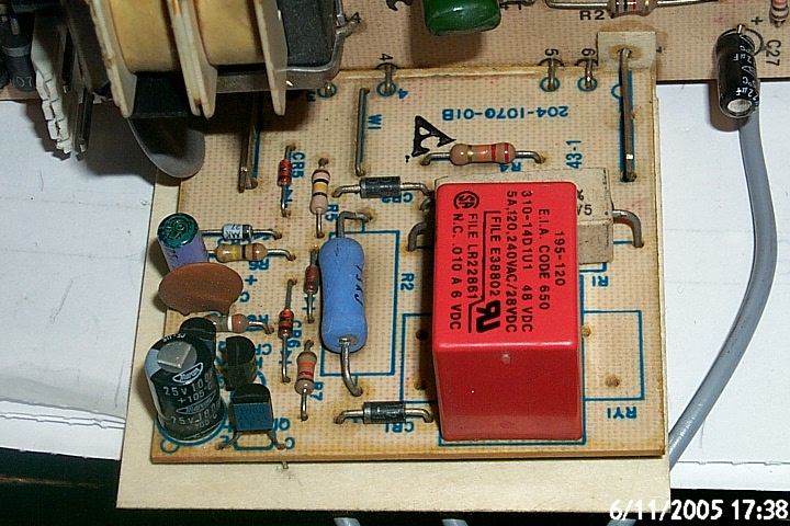
little daughterboards in there. One is an inrush limiter and contains
a relay
that shorts out a power resistor once the smoothing capacitors have charged.
Another contains the overcurrent protection circuit, and, IIRC, a
12V regulator. The last contains the overvoltage protection circuit (the
chips on that board are LM339 quad comparators).
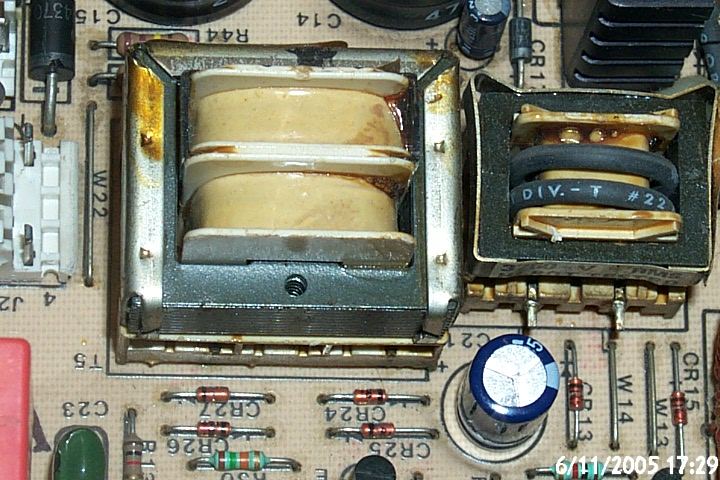
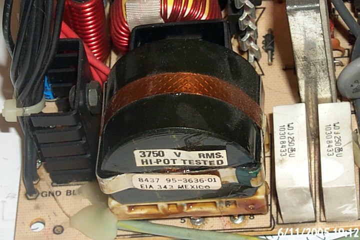
There are 2 protection circuits. One is a
current sensor, there's a current transformer in series with the chopper
transformer primary winding. The other is a set of voltage sensors. Whatever you
do, don't disable any of the trips. If there really is something wrong, the
results would be spectacular!.
(Tony
Duell)
One thing that I've seen on some switchers is something
that watches to see if the transformer/coil core saturates. It is a simple coil
that picks up the stray magnetic fields when the coil is overloaded( that often
causes the blowout current in the switching transistor ). One has this detection
circuit clamp the gate voltage to the switching transistor when it see excess
leakage flux. It works better than a simple current detect because it self
compensates for the cores temperature. If there is a current overload, it will
keep the circuit from powering up. One could put a LED on it to visually detect
the condition.
(Dwight K. Elvey)
Troubleshooting
procedure
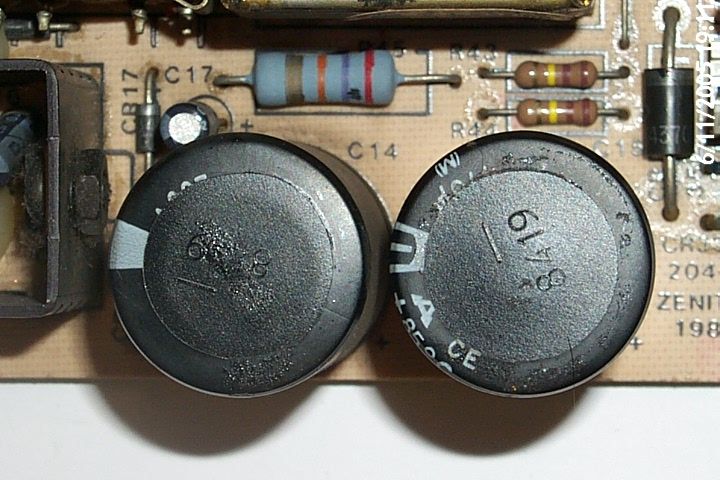
Check
you're getting about 350V DC across the mains smoothing capacitors (2
electrolytics in series)
CHeck
you're getting power to the 3524 (if not, troubleshoot the circuit round
that little transformer you mentioned)
Check
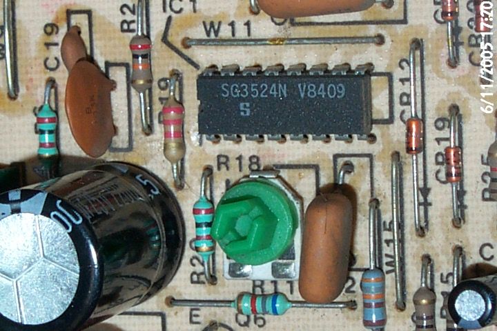
that the 3524 is oscillating.
OK, I've looked at mu schemaitcs. I am asusming this supply is the same
as the one you have.
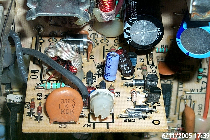
The 3524 supply, at least at startup comes from the mains transformer T5
on the mainboard. C21 (470uF) is the smoothing capacitor for that.
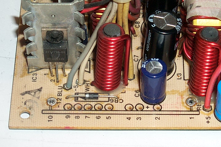
Now, the 3524 is oscillating, but I assume it's producing no output to
the the driver transsitors Q5 and Q6, right? There seem to be 3 possibilites
1) The 3524 is defective
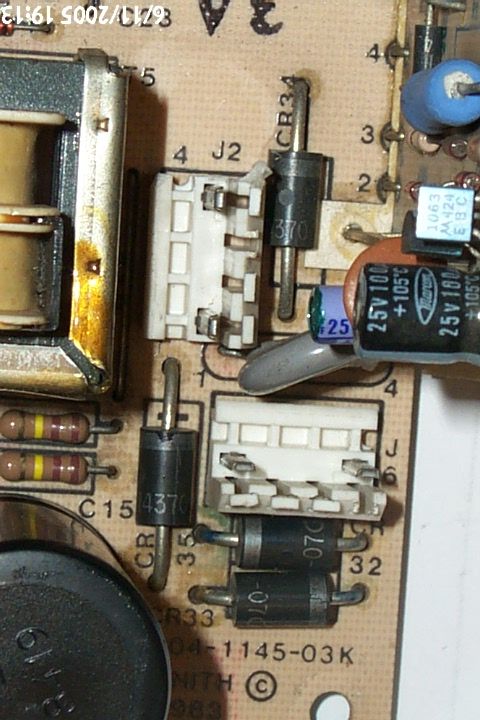
2) It's shut down. The shutdown pin is driven from the SCR CR11 on the
1144-01E PCB. That takes inputs from the current sense circuit and the
overvoltage shutdown. Since you say that the shutdown pin is not asserted (do
check this at the 'other' side of R11, 6k8), I think this is not the problem
weeither.
3) The other way to shut down a 3524 is via the comp pin (compensation).
This is actually the output of the error amplifier, of course. In this
supply, IC2a (LM339) can clamp this pin to ground. It appears this occurs if the
startup voltage is not high enough (the inputs to this chip are the
reference voltage form the 3524 and a potted-down version of the
supply
to that chip).
Data sheet del controller SG3524 della SGS Thomson
Piccolo corso per riparare questo alimentatore
| |
|
| |
|
| |
|
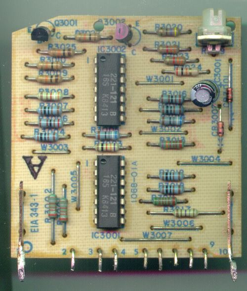 |
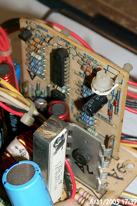
The output of the voltage
protection board is pin 9, that receive signals from CR3001 and CR3002
diodes. Pin 8 is the power supply for the board.
IC3001, IC3002 = LM339
C3001 = 47uF 16V |
 |
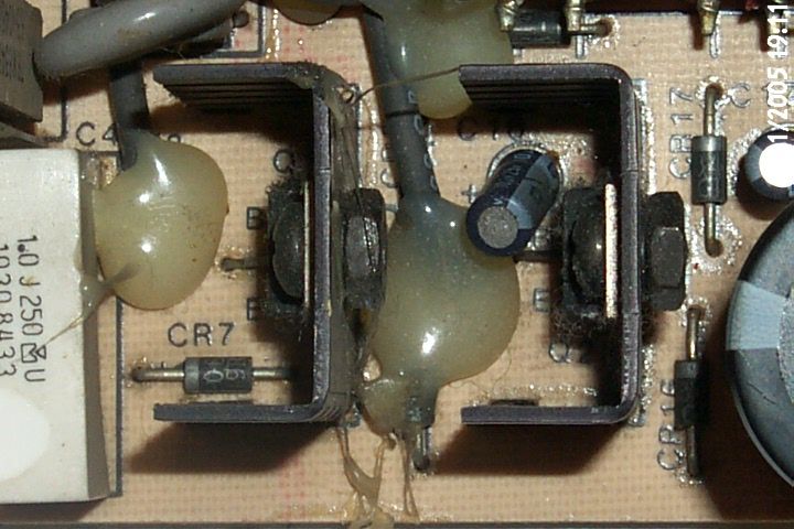
La piastra di controllo
tensioni si inserisce sulla scheda principale in questa posizione. |
| |
|
| |
|
| |
|