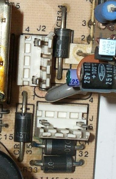
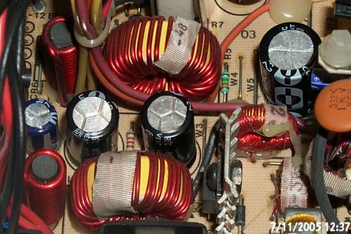
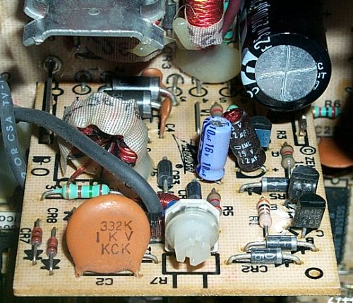
- i diodi del raddrizzatore principale da CR32 a CR35.
- la scheda di limitazione della corrente di spunto
Se i diodi dovessero essere guasti, sostituirli con normali 1N4007
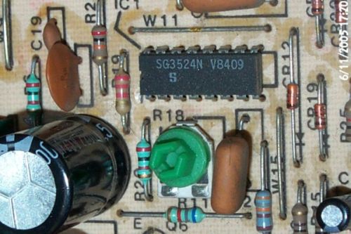
Il condensatore C21 e' da 470uF 16V, nel caso sia in perdita sostituirlo, possibilmente con uno a 105°
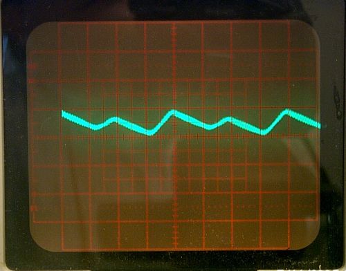
Segnale VRef visualizzato con 2V/divisione di verticale
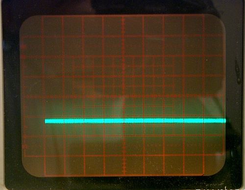
La scala verticale e' di 1V/div
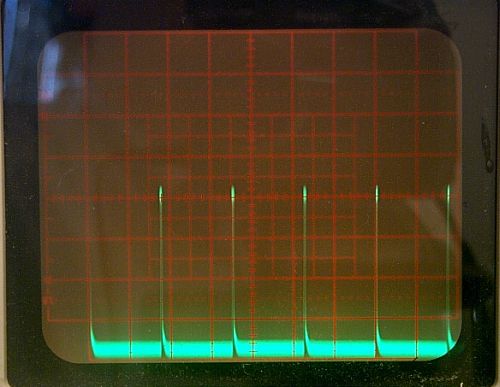
La scala verticale e' di 1V/div
Whatever you do, don't try disabling any of the shutdown circuits.... The results can be spectacular and expensive.
There are 3 possible shutdowns (undervolage, overvoltage, overcurrent) which are diode-ORed together onto the gate of CR11 (the shutdown SCR I mentioned in the last message).
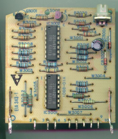
I would look at the 1068-01A voltage limit PCB. There are 2 transistors on that board. Q3002 is cut off (collector goes high) if there's an overvoltage. Q3001 is cut off if there's an undervoltage for too long (R3024 and C3001 act as a delay on this signal).
I think I would check C3001, in case it's shutting the PSU down before it's properly started. Then look at the collectors of Q3002 to see if the thing is detecting an overvoltage.
I think it is just a standard NPN transistor. From what I remember, it had a non-standard 'house number', but something like a 2N3904 will probably work.
As yuo know, there are 8 comparators on this board, 4 for overvoltage and 4 for undervoltage (no, it's not, IIRC, one chip for overvoltage, etc).
You can trace back the sircuit from the base of the each of the 2 transistors to find out which comparators are for each function.
I think what I might do next is get a spare comparactor chip of the same type (LM339) and connect the power and ground pins to the power and ground pins of the chip on the board (I am not _sure_ they both have the same power and ground connections, check this!). Then link the inputs -- right way round -- to each of the 4 comparators in the undervoltage circuit in turn. Put a suitable pull-up resistor (to the comparator power connection on the output). See if any one of the 4 undervoltage comparators appears to have an output that's always low (remember, a low output from the comparator will cut off the transistor and therefore trigger the SCR).
You may find one of the output voltages is not coming up properly.
(courtesy of Tony Duell)
IC3001, IC3002 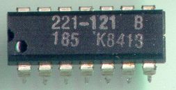 = LM339
regulate the 5V output (that's the one that's fed back to the error
amplifier on the 3524 chip), and the other outputs follow along. If you
don't give the 5V supply enough load, the supply doesn't have to 'work
very hard', and the other outputs tend to be low.
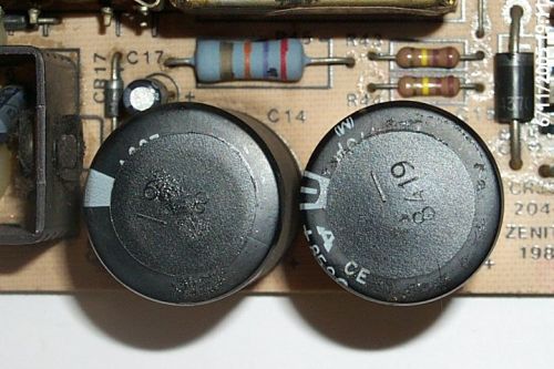
Alos check the output capacitors. A dried up one will cause all sorts of
problems.
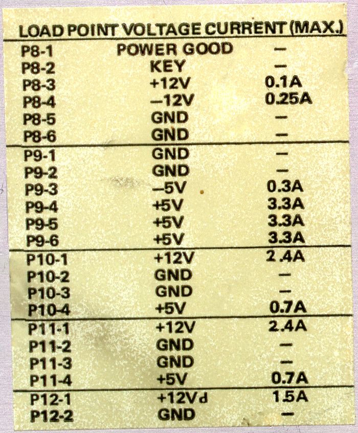
P8 e P9 sono quelli che vanno affiancati ad alimentare la mainboard, P10 e P11 alimentano i drives, P12 il monitor