ERS/FT II Multiplexor
A multiplexor (mux) integrated into the Series II Systems allows a single monitor, keyboard, mouse, and floppy drive to be shared by multiple computers (BC Series plug-in computers) installed in the system. In addition, many of the front panel functions, such as the BC Reset pushbutton, will only affect the selected computer. (The selected computers group number displays on the front panel.)
The multiplexor is a printed circuit board located between the disk drive bay and the processor bay. The mux board is installed vertically and crosswise in the system.
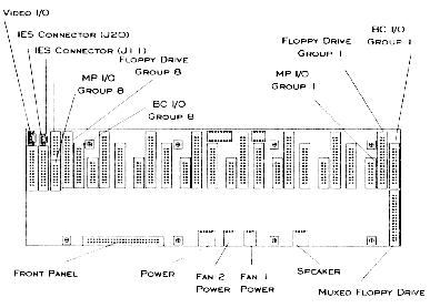
The mux operates on the concept of channels (refer to Figure 3-4 ). There is a separate mux channel for each possible computer (BC Series plug-in computer) in the system, yielding a total of eight mux channels. The mux connects the selected computer to the monitor, keyboard, mouse, and floppy disk drive (these peripherals are referred to as "muxed devices"). An operator may select a computer via the front panel of the system. When a computer is selected, the mux enables the channel corresponding to that computer, allowing the signals for the monitor, keyboard, mouse, and floppy drive to pass through the channel to the selected computer.
In addition to muxing the monitor, keyboard, mouse, and floppy devices between computers in a single system, the multiplexor shares all of these devices except the floppy drive between multiple systems installed in a single Cubix System 1010 cabinet. This allows a single monitor, keyboard, and mouse to service all of the computers in a cabinet. One floppy drive is required per system to service all of the computers in that system.
ERS/FT II Custom Channel
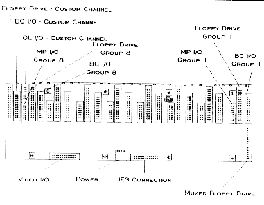
In addition to the eight standard channels on the multiplexor, the ERS/FT II has a ninth channel referred to as the "custom channel" (refer to Figure 3-5 ). This channel is not available on the ERS II. The custom channel may be attached to Cubix QL Series processors, connecting them to the muxed devices for installation purposes. The custom channel may be enabled or disabled via an option switch (refer to the Custom Channel Configuration section in Chapter 4).

Figure 3-4
ERS II Multiplexor (Rear View)

Figure 3-5
ERS/FT II Multiplexor (Rear View)
Show me how to replace a multiplexor
Systems | Circuit Boards | Other Products | Software | Hardware Identifier
Other Vendors | Technical Notes | Downloads | Search | Support Home Page
This document, and all
Web Site contents, Copyright ©
2000 by Cubix Corp., Carson City, NV, USA.