

|
|
PREVIOUS PAGE | 2770 INDEX | WOLLENSAK PRODUCT INDEX | MANUALS INDEX | NEXT PAGE |
|
3.1 MECHANICAL TROUBLESHOOTING
3.1.1 Introduction
The tape transport mechanism must move the tape smoothly along the tape path at a constant speed with a minimum flutter while passing over the magnetic heads. The tape is pulled off the lightly braked supply wheel by the constant speed capstan. The rubber capstan pressure roller supplies sufficient pressure to hold the tape firmly against the capstan. The rotating speed of the take-up spindle is regulated with the Aid of the take-up clutch assembly to provide the uniform tension required for an even tape wrap. Wow and flutter problems are usually associated with faults in the capstan and capstan pressure roller assemblies. Too tight, too loose, or uneven tape wrap problems are caused by binding reel hubs, maladjusted brakes, worn felt pressure pad mounted in each cassette tape and defective power transfer to the reels.
3.1.2
No Tape Drive
Check to see whether the motor is free to rotate.
1.
Are motor leads off?
2. Is the idler jammed or idler spring disconnected not allowing contact
with motor pulley and flywheel?
3.1.3 No Forward or Rewind But Capstan Revolves
1. Check for defective cassette.
2. Spindle tire slipping on motor pulley due to wear or oil on surface.
3.1.4 Take-Up Reel Does Not Turn Although Tape
Feeds Past the Capstan
1 . Take-up idler spring off or broken.
2. Oil or grease on idler and hub of flywheel.
3. "Frozen" spindle.3.1.5 Take-Up Spindle Failed (Weak Take-Up)
1. Check with a known good cassette to determine if the cassette is defective.
2. Grease or oil on take-up idler or flywheel surface. Clean with alcohol or replace.
3. Take-up spindle clutch weak. Replace.
3.1.6 Unit in Constant Rewind
1. Rewind solenoid spring weak or disconnected. Replace or reconnect.
3.1.7 Wow and Flutter
1. Check the unit with known good test cartridge.
2. Check motor for drag or loosened bearings. Check the motor pulley for irregularities which may cause uneven drive.
3. Check drive idler surface.
4. Check the flywheel for wear or drag. Move the idler away from the flywheel. Rotate the flywheel. It should rotate freely. Clean the drive surface to be sure it is free from all contamination such as dirt or oil.
5. Check the pressure roller bearings for wear or drag.3.1.8 Speed Not Correct
1.Check all points as described in paragraph 3.1.7.3. To check the master module insert the I kHz test tape. Go into a duplicate mode and using a frequency counter connected to the Channel I monitor jack check the frequency. Ile counter should read 16 kHz. If more than ± 1%, replace the motor.
3.2 MECHANICAL ADJUSTMENT'S
3.2.1 End-of-Program and Tape Sensing Adjust
1 . Verify that the drive belt is not stretched or broken.
2. Visually check the clearance of the shutter assembly (rotary disc) between the two coils.
3. Coil L-101 and L-102 should be equidistance from the shutter wheel (see Figure 3.1). If not, re-adjust the moveable coil L-101.
Refer to paragraphs 4.1.4 and 4.2.5.
NOTE
Because of the high possibility of accidentally moving L-101 while a module is removed, the above procedure should always be performed after re-assembling a removed module to the console.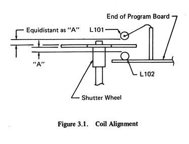
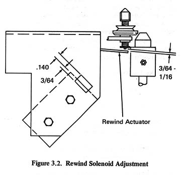
3.2.2 Rewind Solenoid Adjust
1. Adjust rewind solenoid so that approximately 3/64" of the body of the solenoid appears in the window of the bracket.
2. Energize solenoid and observe position of rewind actuator arm in relation to bottom of shaft of rewind spindle assembly.
3. Check that rewind actuator arm clears shaft end by approximately 3/64" to 1/16" spacing when urethane tire is in contact with cone of motor pulley. Readjust solenoid, if necessary, to obtain spacing.
3.2.3 Motor Pulley Height Adjustment
1. This adjustment is only required if a drive motor is replaced.
015 inches below the top surface of the upper mechanical Plate. See Figure 3.2A.
3. Check to insure that lateral position of pulley is such that the rim of the spindle tire is tangent to the rim of the cone at the top of the motor pulley.
4. Check that gap between the spindle tire and the motor pulley is between .015 and .035 inches.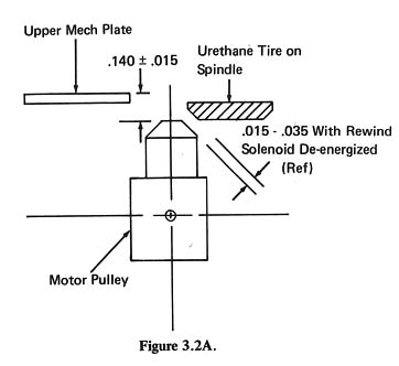
3.2.5 Play Solenoid Adjustment
1 . After replacing a Play Solenoid, adjustment is suggested. Either of the two methods listed below is acceptable.
Mehtod # 1
1 . Exert force against end of solenoid plunger so that Slide Plate [1] impinges against slide plate stop and guide [2] (See Figure 3.2C) and all "play" or looseness is eliminated from the linkages.
2. Move solenoid as required to bottom the solenoid against cone of the plunger and secure three screws
Method #2
1 . Loosen three screws [3] apply power to the unit and cause solenoid to energize.2. Move body of solenoid to the left until all looseness and "play" is eliminated from linkages and slide plate is firnily against the stop.
3. Secure the three screws [3] -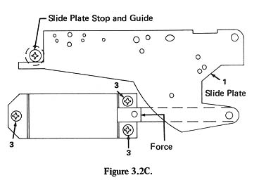
3.2.6 Record or Reproduce Head Replacement (Adjust able Head Mount units only)
2. Remove head and remove head leads insuring to write wire color code on Slide Plate.
3. Install new head and replace two screws [3] removed in step 1 but do not fully tighten.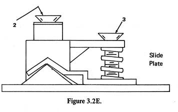
3.2.8 Head Height Check and Adjustment
1 . Use the Wollensak/3M Head Alignment gauge (catalog no. 81-0031-0930-3) or equivalent.
2. Place the gauge plate in the cassette well to be checked. (Cassette well must be in place to insure validity of this test.)
3. Set the notched guide bar on the plate and slide the relieved portion through the tape guide fingers of the head. If height is correct check bar will pass without touching the head guide fingers.
4. Should the head height require adjustment use the plain guide-check bar.
(a) Slide check bar into the head guide fingers.
(b) If check bar is not flat against plate adjust the screw designated [2] in Figure 3.2E until check bar is completely flat against plate surface.
(c) Use notched guide bar and perform step 3 of this procedure.
|
|
PREVIOUS PAGE | 2770 INDEX | WOLLENSAK PRODUCT INDEX | MANUALS INDEX | NEXT PAGE |
|