PREVIOUS PAGE 2770 INDEX WOLLENSAK PRODUCT INDEX MANUALS INDEX NEXT PAGE


SECTION H. PRELIMINARY SERVICE

2.1 GENERAL-ROUTINE CLEANING
AND LUBRICATION

2. 1.1 Head and Capstan


Accumulations of tape residue and other foreign material can cause wow and flutter, impaired erasure, reduced volume, and loss of high frequency response. These deposits -may be found on tape guide posts, capstan, capstan pressure roller, and heads. Perform the following cleaning procedure regularly, at least after every 10 to 12 hours of use.


1 . Remove cassettes.
2. Plug the unit into power source outlet and depress the POWER button

3. Using your left forefinger or thumb, press back and hold the CARTRIDGE INTERLOCK lever located at the left rear of the cassette well.

4. Now, using your right hand, depress the START button to expose the heads.

5. Use a cotton swab moistened in methyl alcohol to clean the front of the heads.

CAUTION
Use only alcohol in cleaning the heads as other cleaning fluids may harm the head assembly. Avoid excess alcohol on adjacent plastic parts. Never touch the heads with a sharp object or anything containing metal.

6. With the unit still running, place the moistened swab on the capstan and pressure roller.

7. Follow the above steps for all three modules.

2.1.2 General Cleaning

Clean the Model 2770AV and/or 2780AV Exteriors with a soft clean cloth. If it becomes very dirty, use a mild cleaner. Avoid excessive rubbing. Never use a thinner or strong chemical solution as this could damage the surface of the case and walnut sides.

2.1.3 Lubrication

The Wollensak 2770AV and 2780AV are factory lubricated. Additional lubrication is not necessary more often than every six (6) months, or before 500 hours of operation. Before applying additional lubrication, remove excess grease that has moved away from the point of lubrication. This grease picks up dirt and grit causing excessive wear or binding when not removed. Lubricate in the following manner:

1 . Re-apply Lubriplate or equivalent sparingly to areas where factory applied lubrication was removed in cleaning. In ideal conditions factory lubrication may last the life of the mechanism.

2. It should never be necessary to apply additional oil to Oilite bearings; but if oil is applied, never use a lightweight machine oil but rather use SAE 20 very sparingly.

2.2 PRELIMINARY TESTS

2.2.1 Introduction

Verify that the unit is not functioning correctly by attempting to operate the equipment as described in Section 1.

1 . Check to see that the AC plug is inserted properly into power outlet.

2. Insert pre-recorded cassettes of known quality into the Master and both Copiers

3. Place the unit in DUPLICATION mode and inspect the tape path.

a. Is the tape wrap on the take-up spindle uniform and level?

b. Is the tape moving smoothly over the heads at a constant speed?

c. Is there abnormal slack in the tape?

4. Place the REWIND selector in MANUAL. The tape should immediately begin to rewind. Check for the following:

a. Is the tape wrap on the rewind spindle uniform and level?

b. Does the tape accelerate smoothly and rapidly onto the spindle?
c. Is there abnormal slack in the tape?

5. Remove the two cassettes from the Copiers, and using a playback recorder (Wollensak Model 26 10 is ideally suited for this purpose), play back the tapes and check for the following:

a. How is the reproduction quality?

b. Is the volume satisfactory?

c. Are there any mechanical noises from the tape mechanism?

d. Are any indications of a previous recording heard?
disambly screws


2.3 DISASSEMBLY

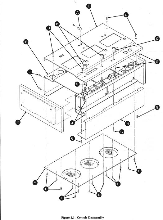
2.3.1 Removal of Top Panel (See Figure 2.1)

1 . Disconnect the AC power cord from outlet
2. Loosen the Phillips screw. and remove the REWIND
SELECTOR knob [A] REMOVE SCREW.
3. Loosen the two set screws and remove the two RECORD LEVEL [B]
4. Loosen the set screw and remove the CHANNEL
SELECTOR knob [C] 5. Remove the four Phillips screws [D] securing the top panel [E] to chassis [F] 6. Lift the top panel up and away from the chassis and place to one side.

2.3.2 Removal of Front Panel (See Figure 2.1)

1. Follow disassembly sequence as described in para graph 2.3. 1 2. Remove the six Phillips screws [G]
3. Remove the front panel [H]and place to one side.

2.3.3 Removal of Sides (See Figure 2.1)

The following procedure is identical for both the right and left side.

1. Follow disassembly sequence as described in para graph 2.3.2.
2. Remove the two front and rear Phillips screws [J] and pull straight out and away
3. Grasp the side [K] from chassis [F] Place the removed side on a cloth to prevent scratching.

2.3.4 Removal of Bottom Panel (See Figure 2. 1)

1 . On a clean soft cloth, stand the unit in the vertical position.
2. Remove the fourteen Phillips screws [L]securing the bottom panel [M] to the chassis [F]
3. Remove the bottom panel.

CAUTION
With the bottom panel removed, DO NOT return unit to the horizontal position. To do so could damage the motor fans. The unit will operate while in the vertical position.

2.3.5 Removal of Mechanical Modules

The following procedure is identical for the PLAYBACK and both RECORD modules.

1. Follow disassembly sequence as described in para graphs 2.3.2 and 2.3.4.
2. On a clean soft cloth, stand the unit upright on its side.
3. Unplug the head cable from the circuit board.
4. Disconnect the six pin motor connector.
5. Unplug the rewind solenoid wire from the spade lug terminal located on the copier circuit board.
6. Disconnect the power socket from the END-OF- PROGRAM circuit board.
7. Remove the four Phillips screws that secure the module to the chass

8. PLAY module only - when removing this module, two additional steps are necessary:
a. On Lot A units disconnect the three spade lugged wires from their respective terminal strips. On issue one models disconnect the Molex connector.
b. Remove the two Phillips screws that secure the END-OFPROGRAM switch mounting bracket. Lift the bracket up and relocate to the rear of the unit.

9. To remove the module, carefully and slowly pull the module straight out and away from the chassis. While removing the module, tuck in all wires that may cause an obstruction.

CAUTION
When setting a removed module down on a work bench, DO NOT rest the module against the motor fan. Damage may result to the fan if the module is improperly handled.

2.3.6 Removal of a Motor (Refer to Figure 3.7)

1 . Follow disassembly sequence as described in para graph 2.3.5.
2. Using a 11/32 open end wrench, remove the four hex nuts [63]
3. Remove the motor [32] from the module.

2.3.7 Removal of Motor Fan
(Refer to Figure 3.7)

1. Follow disassembly sequence as described in para graph 2.3.4.
2. Using a 1/16 Allen wrench, loosen the two set screws [46] (Lot A versions only) on the RECORD module (E Ring on the PLAYBACK module and all issue one units) attaching the fan [33] to the motor shaft.
3. Grasp the fan and slide it off the motor shaft.

PREVIOUS PAGE 2770 INDEX WOLLENSAK PRODUCT INDEX MANUALS INDEX NEXT PAGE


Wollensak 2770 Duplicator Page 15 of 17 updated 07-02-2006