| Tandon TM100 Disk Drive |

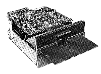
This was the original floppy disk drive for IBM-PCs and compatibles. It used standard 5¼" (133.4mm) diskettes and included
A veritable cornucopia of goodies!
The electronic components of the Drive are mounted on two PCBs, one of which (Logic) is located above the chassis, the other (Servo) is mounted at the rear of the unit.
| Logic PCB |

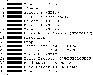
The Interface Connector on the Logic PCB is an edge connector with signals numbered from 2 to 34 on the top surface and grounds numbered from 1 to 33 on the bottom surface.
| Edge Connector Pin Assignments |

Note: Later floppy disk drives have slightly different pin assignments
All interface signals are TTL compatible. Logic true (low) is +0.4v (maximum), logic false (high) is +2.4v (minimum). Maximum interface cable length is 10 feet. It is recommended that the interface cable be flat ribbon cable, with a characteristic impedance of 100 ohms (or equivalent twisted pairs).
| Signals to the Disk Drive Logic PCB |
Drive Motor Enable (NMOTORON)
When this signal line logic level goes true (low), the drive motor accelerates
to its nominal speed of 300 rpm and stabilizes in less than 250 msec. When the
logic level goes false (high), the motor decelerates to a stop.
Direction, Step (NSTEP)
A true (low) pulse with a time duration greater than 200 nsec on the
Step line initiates rotation of the stepper motor. The rotation is
Clockwise if the Direction line is in the true (low) state when a
Step pulse is issued and anti-clockwise if the Direction line is in
the false (high) state. The Direction line should be stable
0.1 µsec (minimum) before the trailing edge of the corresponding
Step pulse and remain stable until 0.1 µsec after the trailing
edge of the Step pulse. The rotation is initiated on the trailing edge
of the Step pulse.
Input Line Terminations
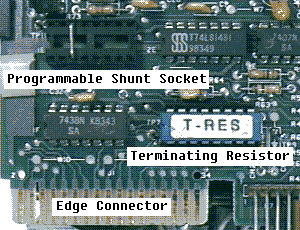
The Drive Motor Enable, Direction and Step lines are
terminated by a 150ohm terminating resistor on the Logic PCB. In a single
drive system, this should be kept in place to provide the proper terminations.
In a multiple drive system (MX open on the programmable shunt socket),
only the last drive on the interface should be terminated. The terminating
resistor must be removed from all other drives.
Select 0-3 (NDS0-NDS3)
These four lines (NDS0-NDS3) select one of up to four Disk Drives
attached to the controller. When the signal logic level is true (low), the
Disk Drive electronics are activated and the Drive is conditioned to respond
to step or read/write commands. When the logic level is false (high), the
input control lines and output status lines are disabled.
A Select line must remain stable in the true (low) state until the execution of a step or read/write command is completed.
The Disk Drive address is determined by a Select Shunt on the Logic PCB. Select lines 0-3 provide a means of daisy-chaining a maximum of four Disk Drives to a controller. Only one line can be true (low) at a time. An undefined operation might result if two or more units are assigned the same address or if two or more Select lines are in the true (low) state simultaneously.
| Programmable Shunt Socket |
=   = HS
=   = NDS0
=   = NDS1
=   = NDS2
=   = NDS3
=   = MX      Multiplex option *
=   = SPARE
=   = HM
* if this is open, multiplexing of the I/O lines is allowed.
| Signals from the Disk Drive Logic PCB |
Index (NINDEX/SECTOR)
The index circuitry consists of an LED, Photo Transistor, and a Pulse Shaping
Network. When light from the LED strikes the Photo Transistor causing it to
conduct, a signal is sent to the Pulse Shaping Network which produces a pulse
on the Index Pulse Interface line. The Index line remains in the true (low)
state for the duration of the pulse.
Track 00 (NTRK00), Write Protect (NWRITEPROTECT)
These signals go low (true) when the corresponding microswitches are depressed.
| DC Power Requirements & Connector Pin Assignments |
+12 ± 0.6v dc: 900 MA (MAX AVE.)
+5 ± 0.25v dc: 600 MA (MAX AVE.), < 100mv P.P. ripple

| Other Sources of Information |
|
last updated: 26-Aug-97 Ian Harries <ih@doc.ic.ac.uk>