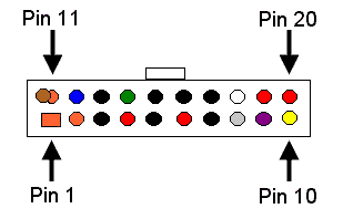


Please note that this connector's pins are numbered oddly - not in the normal manner Instead it is numbered like the odd-ball Sub-d connector. Probably someone who had not laid out many PCBs did this. (A normal approach would have been to number it counterclockwise looking at the sockets or clockwise looking at the pins)
| Pin | Signal | Wire Color |
|---|---|---|
| 1 | +3.3Vdc | Orange |
| 2 | +3.3Vdc | Orange |
| 3 | GND | Black |
| 4 | +5Vdc | Red |
| 5 | GND | Black |
| 6 | +5Vdc | Red |
| 7 | GND | Black |
| 8 | PWR-OK | Gray |
| 9 | +5Vdc VSB standby Voltage |
Purple |
| 10 | +12Vdc | Yellow |
| 11 | +3.3Vdc | Orange {brown is 3.3Vdc sense] |
| 12 | -12Vdc | Blue |
| 13 | GND | Black |
| 14 | PS-ON | Green |
| 15 | GND | Black |
| 16 | GND | Black |
| 17 | GND | Black |
| 18 | -5Vdc | White |
| 19 | +5Vdc | Red |
| 20 | +5Vdc | Red |
 |
3209 W.9th street Lawrence, KS 66049 USA |
Ph |
(785) 841 3089 (785) 841 0434 inform@xtronics.com http://xtronics.com |
Bookmark
this page
|
| Transtronics Home Page See our line of industrial control electronics |
PLC's Index | PC test equipment and EPROM programmer | Process Control Panel meters |
Current sensors | Resource library handbooks, primers and spec sheets |
Corporate
information
and
privacy statement
(C) Copyright 1994-2006,
Transtronics, Inc. All rights reserved
Transtronics® is a registered trademark of Transtronics, Inc.