Motorola MC68705P3 mcu reader / copier /
programmer
![]()
Note: Reading operates at 4 Mhz Speed (Switch I2 in Position
0) in order to divide by 4 the read-out.
If one 68705P3 append to be hard to read then operates at 1Mhz Speed.
The extraction of the program is done by consecutive verifications : This
task that can take up to 3 days is very reduced howing to a powerful algorithm.
Depending on the memory used in the microcontroller, it can takes from few
hours to a dozen of hours.
 |
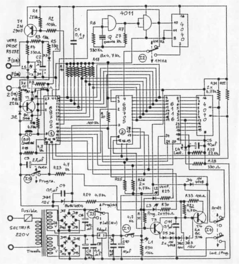
MC68705P3S reader tool:
The diagram is given here : The SRAM 6116 can be replaced by the M48Z02 (or MK48Z02) Zeropowerram from ST , so that it can be read by a universal devices programmer.
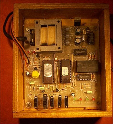
This tool is a dedicated reader / copier tool that allow to read out
the MC68705P3 mcu. |
STANDALONE OPERATION:
READING OF THE MC68705P3:
Put Switch I5 on Position AUTO (0)
Put Switch I2 on position 4 Mhz (0)
Plug the power
Put the 68705P3 containing the program to read in the Socket "2"
Put Switch I3 on position 12 Volts (0)
Put Switch I1 on position 5 Volts Operation (1) : Led L1 lights on
Put Switch I4 on Position Lect/Prog (1)
Press the key BP during a second then Led Led blinks every half seconds and
led L4 blinks very quickly. Reading is starting , extrcating the program in
the SRAM.
At the end of the reading Led L2 L3 stay lit but L4 is lit off
Put I4 switch in position Stop (0)
Put I1 in position Stop (0) Led L1, L2, L3 light off
Put away the MC68705P3 that has been read.
PROGRAMMING AN EMPTY MC68705P3
Fix the empty device on socket 2
Put switch I2 on position 1MHZ (1)
Put Switch I3 on Position 25Volts (1)
Put switch I1 on Position Operation 5Volts (1) : Led L1 light on.
Put Switch I4 on position lect/Prog (1)
Put Switch I5 on Position Prog (1) : Led L4 blinks every 5 seconds approx. and
indicates that programming is in progress during 1mn 30s approx.
At the end of the programming, the led L3 lights on In the case the programm
has been transfered all right, Led L2 should light on 1 second after and indicates
the verification is OK Led L4 stops blinking.
Put Switch I5 on position Auto (0) : Led L2 & L3 light off
Put I4 on position Stop (0)
Put I1 on Position Stop (0) : Led L1 lights of Remove the programmed 68705P3.
Power Supply : the power supply is done by a 5VA Transformer with 2 voltages 24 Volts and 9 Volts : the power does not exceed 5 Watts approx.
Components side:
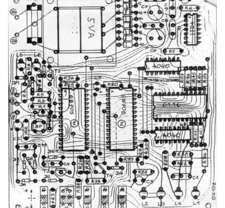
Diagram (schematic available here ![]() 68705p3.pdf (49 Kb) )
68705p3.pdf (49 Kb) )
![]() Diagram & Component (better scan version)
(269Kb)
Diagram & Component (better scan version)
(269Kb)
In order to work to the software lect-p3 you need the following connexion
Use de DB25 to DB9 adaptor if necessary.
DB25 -
(2) TX
(3) RX
(7) GND + Connect (4) & (5) each other ; Connect Also (6) , (8) & 20
each other. this allow the software to recognise if the programmer is plugged
or not.
Components List
Transformer 5VA 2 outputs : 24 Volts and 9 Volts
Regulator 5 Volts L7805CV
Fuse 1.5A 250V and Fuse socket
Programmed MC68705P3(1)
2 x 28 pin Sockets , 1 x24 pin Socket ZIF Socket Optionnal
1 SRAM 6116 or ZEROPOWER RAM M48Z02-70PC1 (contains lithium cell 10 years) that
can be read by a universal programmer.
CMOS ICs : 4040 x2, 4011 x1
5 SWITCHES ON-OFF 3 connexions
Transistors T2,T3,T4 : BC546
Transistor T1: 2N2907A
L1, L3, L5, L6 3mm Red Led
L2, L4 3mm Green Led
DZ2 BZX85C10 Zener
DZ1, DZ3 BZX85C12 Zener
1N4004 x 8 , 1N4148 x8
R33 :100 OHMS
R4, R5, R28 : 330 OHMS
R29, R30 470 OHMS
R9 : 820 OHMS
R3, R34 : 1KOHM
R10 TO R19, R19 - 21 TO 26 631 - 32 4K7OHMS
R2 10KOHMS
R1- R8- R27 22KOHMS
R7 : 27KOHMS
R20 : 100KOHMS
R6: 330KOHMS
C1-C4-C8-C9-C11 100 NF
C3 2.2µF/POL
C2-C5-C10 10µF/POL
C6 100µF/POL
C7 470µF/POL
Assembling:
No PCB is available at the moment : I advise you to use the Wire-Wrap method or wire method.
![]()
![]() How
to read MC68705U3 EPROM by Peter Ihnat A method to read the EPROM contents
of a programmed MC68705U3/R3
How
to read MC68705U3 EPROM by Peter Ihnat A method to read the EPROM contents
of a programmed MC68705U3/R3
![]()
Other Resources:
*******
If you look forward for other information about this MC68705P3 Reader, do not
hesitate to contact me by e-mail at: matthieu.benoit@free.fr
.
Si vous recherchez des informations pour ce lecteur de MC68705P3, vous pouvez me contacter par e-mail : matthieu.benoit@free.fr . De même si vous avez des informations sur ce programmateur, n'hésitez pas à contribuer à cette page.
![]() décembre 10, 2010
décembre 10, 2010
 68705p3.pdf
 Retour au sommaire
 Retour
à la Page d'accueil
Retour
à la Page d'accueil matthieu.benoit@free.fr