 |
|
|
|
Chapter 2
Hardware
The Cubix Resource Subsystem consists of five main sections. The Power Supply Bay houses a 350 watt power supply which provides power to the subsystem. The ISA Processor Bay contains the 16-slot segmented passive backplane. The Multiplexor Panel provides power distribution and multiplexing functionality to the subsystem. The Disk Drive Bay will support up to nine third-height 3.5" disk drives. The Auxiliary Junction Panel is an option which provides space for auxiliary I/O adapter boards to be installed.
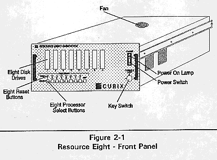
Figure 2-1 Resource Eight - Front Panel.
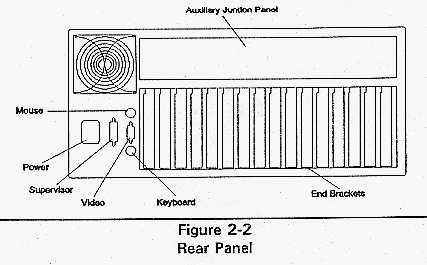
Figure 2-2 Rear Panel.
All Resource Subsystems contain one internal 350 watt switching power supply.
This supply is fan cooled. When the power supply load is properly limited to 350 watts average, and the ambient operating temperature of the subsystem is maintained between 0°C and 40°C, the power supply will provide long trouble-free service.
Load Considerations
The Resource Subsystems have four available voltage sources: +5 vdc, +12 vdc, -12 vdc, and -5 vdc. The subsystems provide the following power levels for each of these four voltage sources.
                     Table 2 - 1
      350 Watt Power Supply Ratings

           +5V@ 50A = 250 watts maximum

       +12V @ 16A  = 192 watts maximum (Peak)

         +12V @ 8A  =  96 watts maximum (Steady State)

         -12V @  5A  =  60 watts maximum

           -5V @  5A  =  25 watts maximum

 Steady State Total Power Available = 350 watts maximum
 Peak Total Power Available = 400 watts maximum

! Peak power is defined as the power required during the IDE
hard
disk drive ramp-up time.  This time is normally 10 seconds
or
less.
The user must ensure that no single voltage source power rating exceeds the maximum listed in Table 2-1. In addition, these maximums are limited by the fact that no more than 350 watts total power may be drawn from all voltage sources combined. It is the responsibility of the user to verify that the sum of the power drawn from the four sources does not exceed 350 watts.
The most straight forward method to determine if the power supply is capable of furnishing sufficient power is to add the power required for each voltage and calculate the total power using the power requirements in Table 2-2.
2 Table 2 - 2
Power Requirements (Watts)
Device           +5V      +12V
-12V      -5V

QL 1044          12.0      1.0       0.6      -----

QL 2220          13.0      0.5       0.3      -----

QL 3001SX***     11.0      0.5       0.4      -----

QL 3001CX***     12.5      0.5       0.4      -----

QL 3002SX***     15.5      1.0       0.8      -----

QL 3002CX***     18.5      1.0       0.8      -----

QL 4001DX/33     17.5      0.6       0.6      -----

QL 4001SX/25     17.5      0.6       0.6      -----

BC               13.0      0.6       0.6      -----
3030SX/25***

BC 4000DX/33     21.0      0.6       0.6      -----

BC 4030DX/33     16.0      0.6       0.6      -----

BC 4030SX/25     14.5      0.6       0.6      -----

Floppy Disk     4.0        -----     -----    -----

Hard Disk       3.0       13.0*      -----    -----
(IDE, 100 MB)             6.5**

Hard Disk       3.0       36.0*      -----    -----
(IDE, 500 MB)             18.0**

Hard Disk       4.0       52.0*      -----    -----
(SCSI, 500 MB)            24.0**

Fan                -----  10.0       -----    -----

Ethernet NIC    5.0        0.5       0.4      0.5

Token Ring NIC  4.0        0.2       -----    -----


* Peak
** Steady State
*** These power figures are with the math coprocessor
installed.  Subtract
     1.0 watt on the +5 vdc if not installed.
For example, Table 2-3 illustrates the typical power requirement for a Resource Eight Subsystem.
Since each voltage and the total power consumption is less than the allowed maximum power consumption, the configuration in Table 2-3 can be properly powered with the 350 watt power supply.
3 Table 2 - 3
Resource Eight Subsystem
Typical Power Requirements (watts)
Device Type    Qty    +5V   +12V
 -12V    -5V
                                                  Total

BC 4030DX/33   8      128    4.8    4.8           137.6
                                            -----

Token Ring     8             1.6    -----
                     32                     ----- 33.6

Floppy         1             -----  -----         4.0
                     4                      -----

Hard Disk      8                    -----
 (IDE, 100           24     104.0*          ----- 128.0
MB)
                            52.0**

Total                 188           4.8
                            110.4*          ----- 303.2

                            58.4**

Maximum               250   192*     60.0
Allowed                      96**           25.0  350.0


* Peak
** Steady State
This section contains a passive 16-slot ISA compatible backplane.
Power for the backplane is provided through a nine position barrier strip, located on the right end of the backplane. Three positions provide +5vdc, and two positions provide +5vdc ground. +12V, -12V, and -5V are each powered with a single line and a single ground referenced to +5vdc ground.
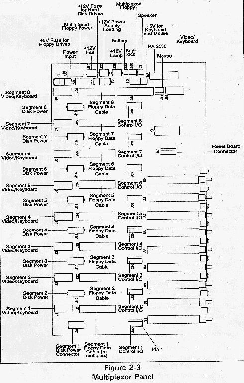
The multiplexor panel distributes power, battery, and speaker signals to components within the Cubix Resource Subsystem. It also multiplexes a single monitor, keyboard, mouse, and floppy diskette drive for use by each segment in the subsystem. Refer to Figure 2-3 for an illustration of the multiplexor panel.
The multiplexor panel is a component in all configurations of the Resource Subsystem. Its purpose is to provide the following functions which are required by segmented backplane technology:
Power Supply Distribution
Power is input to the panel from the power supply via connector J18. The multiplexor panel distributes this power to provide power for the disk drives. Connectors J9 - J16 on the multiplexor panel provide power for disks installed for segments 1 - 8, respectively. If a multiplexed floppy disk drive is installed, it derives power from connector J17 on the multiplexor panel.
The power is also distributed to a 12 volt fan (J19) and the Power On lamp (J29) on the front panel of the Resource Subsystem. Additional power is supplied via J20 to a resistor which assures that the power supply maintains a 12 volt output.
Battery Power Distribution
Connector J30 is attached to a 6 volt battery. The power from the battery is distributed through pin 7 of connectors J32 - J39, which provide battery backup for the CMOS on each BC Series processor. A complete definition of connectors J32 - J39 is included later in this section.
Figure 2-3 Multiplexor Panel.
Video/Keyboard/Mouse Multiplexor
A single VGA monitor, PS/2 keyboard, and PS/2 mouse may be shared by all of the BC Series processors installed in a Resource Subsystem. The Mini-DIN 6 and DB-15 High Density connectors are located on the rear panel of the Resource Subsystem (refer to Figure 2-2).
The monitor and keyboard are cabled from the rear panel connectors to J44 on the multiplexor panel. The mouse is cabled to J41.
In addition to physically attaching the monitor, keyboard, and mouse to the multiplexor panel, the video/keyboard and mouse I/O for each BC Series processor must also be connected. Each BC Series processor installed in segments 1 - 8 is equipped with a video/keyboard header which is connected to J1 - J8 on the multiplexor panel, respectively. A mouse header on each board is connected to pins 1 and 2 of connectors J32 - J39 (a complete definition of connectors J32 - J39 is included later in this section.)
To connect the monitor, keyboard, and mouse to a specific BC Series processor, press the Processor Select button corresponding to the segment containing that processor board. The Processor Select buttons are located on the front panel of the Resource Subsystem (note that they control connection of the floppy drive as well).
When the Processor Off button is pressed or the keyswitch is in the Locked position, the monitor, keyboard, and mouse are disconnected from the BC Series processors.
Floppy Diskette Multiplexor
A single third-height 3.5" floppy diskette drive may also be shared by all of the BC Series processors installed in a Resource Subsystem. If a multiplexed floppy is installed, its power cable is connected to J17 and its data cable to J40 on the multiplexor panel.
The floppy drive I/O for each BC Series processor is also connected to the multiplexor panel. Each BC Series board installed in segments 1-8 is equipped with a floppy drive header which is connected to J21-J28, respectively.
F If a floppy diskette drive is installed for each BC Series processor in the system, there is no need to utilize the floppy multiplexing capability of this panel. In this case, the floppy drives should be cabled directly to the BC Series processors they are to service. Connectors J17, J40, and J21 - J28 are not used.
To connect the floppy diskette drive to a specific BC Series processor, press the Processor Select button corresponding to the segment containing that processor board. The Processor Select buttons are located on the front panel of the Resource Subsystem (note that they control connection of the monitor, keyboard, and mouse as well.)
When the Processor Off button is pressed, the floppy diskette drive is disconnected from the BC Series processors. The position of the key switch does not affect the multiplexed floppy drive.
Speaker
The BC Series processors installed in the Resource Subsystem can share a single speaker output. An eight ohm permanent magnet type speaker is attached to J31 on the multiplexor panel. The speaker output of each BC Series processor is connected to pin 6 of connectors J32 - J39 (a complete definition of connectors J32 - J39 is included later in this section).
Supervisory Support
If the optional Cubix PA 3030 Supervisor board is installed in this subsystem, it must be directly connected to the multiplexor panel via connector J43. If the Supervisor board is installed in a different subsystem, the supervisor connector on the rear panel of the subsystem containing the PA 3030 should be connected to the rear panel of this subsystem. Another cable should internally connect the rear panel connector on this subsystem to the multiplexor panel (J43).
Processor Reset
The multiplexor panel provides the ability to reset the BC Series processors installed in the Resource Subsystem. A board containing the Reset buttons is installed immediately above the multiplexor panel and is connected to the panel via J42. Eight Reset buttons corresponding to the eight backplane segments are accessible from the front panel. To reset a processor, press the appropriate Reset button using a pointed device such as a pen (the buttons are recessed to avoid accidental resets).
When the key switch is in the Locked position, the Reset buttons are disabled. Note that the Processor Select and Processor Off buttons have no effect on the reset function.
Key Switch
A key switch is located on the front panel of the Resource Subsystem. When in the Locked position, the monitor, keyboard, and mouse are effectively disconnected from the BC processors. The Reset buttons are also disabled. When in the Unlocked position, all functions of the multiplexor panel are fully functional. The key switch is connected to the multiplexor panel via J45.
I/O Control Connectors (J32 - J39)
One I/O control connector is located on the multiplexor panel for each Resource Subsystem segment. These connectors are cabled to the BC Series processors as defined in Table 2-4.
Table 2 - 4
I/O Control Connectors
Pin Number         Function

1 - 2              Mouse multiplexor interface

      3 - 4           Supervisor support (PA 3030)

        5               BC processor reset input

        6                        Speaker

        7               Battery power input to BC
                                processor

8                  Ground


! Pin 1 of each connector is closest to the front panel.
Refer
to Figure 2-3.
The disk drive bay is capable of containing nine third-height 3.5" disk drives. This provides the capacity for one hard drive per segment (the maximum number of segments is eight) plus one multiplexed floppy drive. For installations not requiring hard disk drives, the disk drive bay can accommodate one floppy drive per segment.
Each disk drive requires two connections: one for power and one for data. In all subsystem configurations, the disk drives derive power from a connector on the multiplexor panel.
With the exception of a multiplexed floppy drive, the data cables for all disk drives installed in the subsystem are connected directly using a 34-pin ribbon cable from the drive to the BC Series processor utilizing the drive. Since the multiplexed floppy can service multiple BC Series processors, its data cable connects to the multiplexor panel. The floppy drive data cables connect from the BC Series processors to the multiplexor, which controls the drive usage. These cables are one-to-one 34-pin ribbon cables.
Any of four styles of optional auxiliary junction panel may be installed in the Resource Subsystems. The Auxiliary Junction Panel is installed in the back panel of the subsystem above the ISA I/O panel. The auxiliary junction panel allows the user to customize solutions to a wide range of I/O requirements.
Since the amount of space for I/O connectors on the edge of each processor board is limited, board manufacturers must determine which I/O functions supported by the board will be accessible via an on-board connector and which functions will require an off-board connector. The auxiliary junction panel provides a location to install these off-board connectors.
The Cubix processor boards provide several I/O functions with internal headers. To access the I/O, these headers must be connected to an I/O adapter printed circuit board (PCB) designed for this purpose. This adapter board contains the standard connector to interface the internal header with the auxiliary I/O, and should be installed in an auxiliary junction panel on the Resource Subsystem.
Following are illustrations of each style of the auxiliary junction panel.
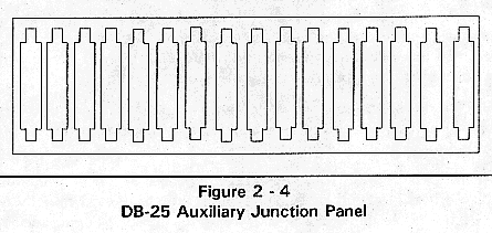
The panel illustrated in Figure 2-4 provides space to install up to sixteen DB-25 connectors. Typically this panel is used with Cubix QL Series processors to provide parallel printer support.
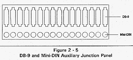
The panel illustrated in Figure 2-5 provides space to install up to sixteen DB-9 and sixteen Mini-DIN connectors. Typically this panel is used with Cubix QL Series processors to provide video and keyboard support.
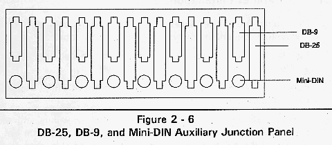
The panel illustrated in Figure 2-6 provides space to install up to eight DB-25, eight DB-9, and eight Mini-DIN connectors. Typically this panel is used with Cubix BC Series processors to provide parallel printer, COM2, and mouse support.
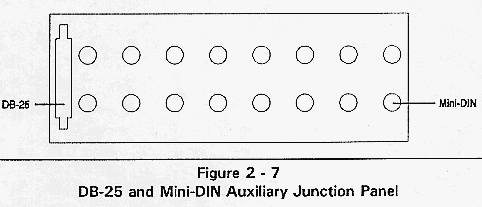
The panel illustrated in Figure 2-7 provides space to install up to sixteen Mini-DIN connectors and one DB-25 connector. Typically this panel is used to provide QL mouse support and printer support for the host processor.
The Cubix Resource Subsystem adheres to the specifications for standard 19" wide RETMA mounting positions. It can be installed in a Cubix System Cabinet or in any enclosure adhering to the 19" RETMA specification.
System Cabinet Installation
1. Determine the proper location in the System cabinet for the subsystem, depending on the system configuration.
2. Install the two cabinet mounting rails in the cabinet. Use the screws provided.
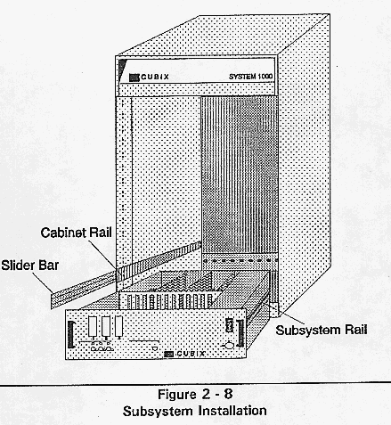
3. Pull the slider bars out of the cabinet rails until they lock into place (Figure 2-8).
4. Carefully align the subsystem rails with the slider bars and slide the subsystem in until it locks into place. Do not let the entire weight of the subsystem rest on the slider assembly until it is in place.
5. To slide the subassembly into the cabinet, press the locking buttons on each side of the slider assembly.
6. Repeat this procedure for each additional subsystem.