 |
|
|
|
Chapter 1
Introduction
The Cubix Resource Subsystem is a rack mount unit designed for installation in a Cubix System cabinet. This subsystem provides single or multiple network workstations in a small and controlled environment ideal for remote communications, fax servers, e-mail servers, mainframe gateways, and NLM servers. Up to four Cubix Resource Subsystems may be installed in a single System cabinet.
The Resource Subsystem is available in several configurations. Following is a description of the major components of the Resource Subsystem technology.
Cubix Bus Controller
The Cubix Bus Controller (BC Series) products provide complete computer solutions on single plug-in boards. Each BC Series board contains a CPU, system memory, VGA video support, a keyboard controller, serial and parallel ports, and diskette drive and IDE hard drive controllers. When installed into a passive backplane, and with the addition of a network interface controller (NIC) in one of the backplane's expansion slots, the BC Series board becomes a network workstation.
Passive Backplane
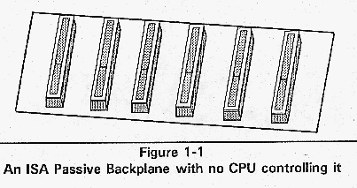
The Resource Subsystem contains a 16-slot passive backplane. The backplane is simply a row of standard 16-bit ISA expansion slots. Adding a Cubix BC Series processor to the backplane creates a single workstation.
Figure 1-1 An ISA Passive Backplane with no CPU controlling it.
Segmented Passive Backplanes
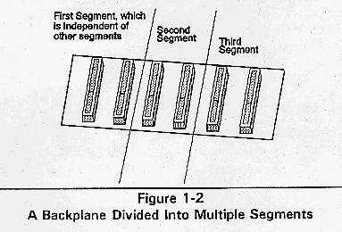
All expansion slots in a passive backplane are interconnected with electronic traces, creating a bus. If these traces are removed, the backplane's expansion slots can be grouped into smaller independent backplanes, or segments.
Figure 1-2 A Backplane Divided Into Multiple Segments.
The Cubix Resource Subsystem contains a standard ISA passive backplane divided into segments. Also included is a disk drive bay capable of housing nine 3.5" disk drives. Since the backplane is a standard ISA component, PC-compatible boards (such as network interface controllers) are supported. With a BC Series bus controller card and a network interface controller (NIC) inserted into each segment, the Resource Subsystem can provide multiple network workstations in a single unit. The number of workstations and expansion slots depend upon the configuration of the 16-slot backplane.
The Resource Subsystem is available in several configurations:
Resource Two
A 16-slot segmented backplane with two segments. One segment contains six slots, and the other segment contains ten slots. With a BC Series board installed in each segment, the Resource Two is functionally equivalent to one AT-class computer with five expansion slots plus one computer with nine expansion slots.
Resource Three
A 16slot segmented backplane with two segments of three slots each plus an additional ten slot segment. With a BC Series board installed in each segment, the Resource Three is functionally equivalent to two AT-class computers with two expansion slots plus one additional computer with nine expansion slots.
Resource Four
A 16slot segmented backplane with four segments. Each segment contains four slots. With a BC Series board installed in each segment, the Resource Four is functionally equivalent to four AT-class computers, each with three expansion slots.
Resource Five
A 16-slot segmented backplane with two segments of two slots each plus three segments of four slots each. With a BC Series board installed in each segment, the Resource Five is functionally equivalent to two AT-class computers with one expansion slot and three computers with three expansion slots.
Resource Six
A 16-slot segmented backplane with two segments of two slots each plus four segments of three slots each. With a BC Series board installed in each segment, the Resource Six is functionally equivalent to two AT-class computers with one expansion slot and four computers with two expansion slots.
Resource Seven
A 16-slot segmented backplane with six individual segments of two slots, plus an additional four slot segment. With a BC Series board installed in each segment, the Resource Seven is functionally equivalent to six AT-class computers with one expansion slot plus one additional computer with three expansion slots.
Resource Eight
A 16-slot segmented backplane with eight individual segments of two slots each. With a BC Series board installed in each segment, the Resource Eight is functionally equivalent to eight AT-class computers, each with one expansion slot.
Table 1-1 Configuration Summary
 Description   Total     Number of
Slots per    3.5"
               Slots     Segments
               Segment     Disk
                                                   Bays


Resource Two     16          2       One 10-slot     9
                                       segment;
                                      One 6-slot
                                       segment

Resource         16          3        Two 3-slot     9
Three                                 segments;
                                     One 10-slot
                                       segment

Resource         16          4            4          9
Four

Resource         16          5        Two 2-slot     9
Five                                  segments;
                                        Three
                                        4-slot
                                       segments

Resource Six     16          6        Two 2-slot     9
                                      segments;
                                     Four 3-slot
                                       segments

Resource         16          7        Six 2-slot     9
Seven                                 segments;
                                      One 4-slot
                                       segment

Resource         16          8            2          9
Eight
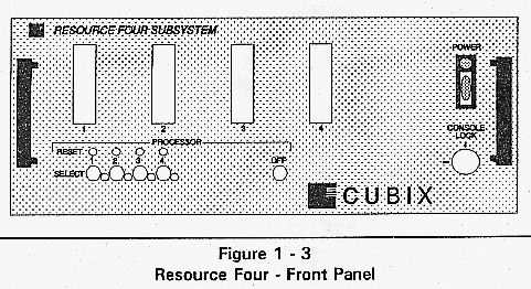
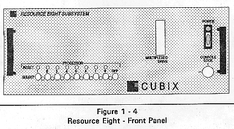
The front panel of the Cubix Resource Subsystem provides a Power On indicator, subsystem power switch, select buttons, a key lock switch, one or more processor reset buttons, and access to one or more diskette drives.
Figure 1-3 Resource Four - Front Panel.
Power On Indicator
Illuminates when power is applied to the subsystem.
Power Switch
Controls application of power to the subsystem.
Select Buttons
All Resource Subsystem configurations have a row of Processor Select buttons. These buttons determine which BC Series processor is controlled by the multiplexor.
Multiplexor
In all of the Resource Subsystem configurations, a multiplexor is available that can be used to switch the following functions on each workstation:
VGA Video
Keyboard
PS/2 Mouse
Diskette Drive
The multiplexor allows a single monitor, keyboard, mouse, and/or diskette drive to be shared by all of the workstations in the Resource Subsystem. These devices are connected to the multiplexor, which is connected to each BC Series processor installed in the subsystem. The Processor Select buttons on the front panel of the subsystem allow the user to select a specific processor. The monitor, keyboard, mouse, and diskette drive function as if they were directly attached to the selected processor. The multiplexor is intended for maintenance and installation purposes. It eliminates the need to acquire these peripheral devices for each workstation in the Resource Subsystem.
Key Lock Switch
There is a key lock switch on all configurations of the Resource Subsystem. Placing the key switch in the Locked position inhibits operation of the reset buttons. It also effectively disconnects the video, keyboard, and mouse devices from the multiplexor.
Reset Buttons
One Reset button is provided for each segment in the Resource Subsystem. The reset buttons are labeled by processor segment number (1 - 8). Pressing the Reset button resets the BC Series processor installed in the corresponding segment. Other segments are not affected. The Reset buttons are recessed to avoid accidental resets; use a pointed device such as a pen to reset a BC Series processor.
Resource Subsystems are available in both hard drive and floppy drive configurations.
Hard Drive Configurations
Figure 1-4 Resource Eight - Front Panel.
If hard drives are required, a single floppy may optionally be shared with the BC Series processors in each segment. Therefore, subsystems configured for hard drives still provide access for one multiplexed floppy drive. A filler panel is inserted in this opening if the multiplexed floppy drive option is not included in the subsystem.
Hard Drive Configurations with Supervisor Option
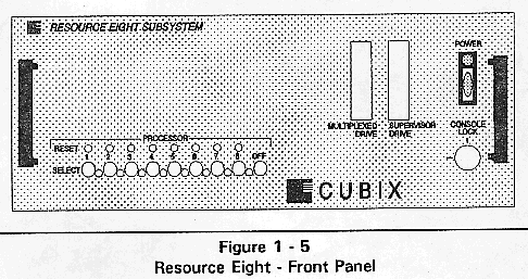
Figure 1-5 Resource Eight - Front Panel.
A Cubix Supervisor processor may optionally be installed in a Resource Five, Six, Seven, or Eight Subsystem. The Supervisor requires a dedicated floppy drive. Therefore, Subsystems configured for hard drives with a Supervisor processor installed provide access for two floppy drives on the front panel: one for the multiplexed floppy drive and one for the Supervisor floppy drive.
! Installation of a Cubix Supervisor processor in a Resource Two, Three, or Four Subsystem is not supported.
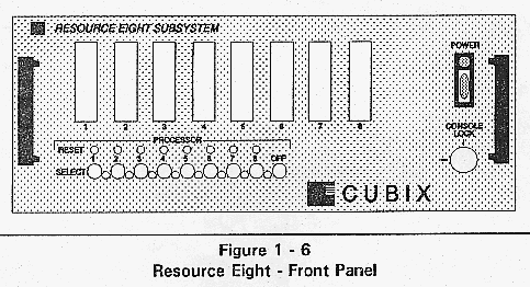
Floppy Drive Configurations
Figure 1-6 Resource Eight - Front Panel.
If hard drives are not required for the BC Series processors, access for one diskette drive per subsystem segment is provided on the front panel. Since this configuration provides one dedicated floppy drive per segment, it accommodates support for the Cubix Supervisor processor.
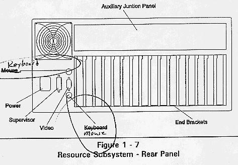
Figure 1-7 Resource
Subsystem - Rear Panel.
F The supervisor connector is optional.
The rear panel of the Resource Subsystem provides access to
the
power receptacle, the end brackets of the installed boards,
the
multiplexed monitor, mouse, and keyboard connectors, the
Cubix
Supervisor connector, and the optional auxiliary junction
panel
(refer to Chapter 2 for a description of the auxiliary
junction
panel).