|
|
|
|
DP 7400/7500 Series
Quick Reference Guide
Jumper Settings
 |
|
Jumper |
Function |
Jumper 1-2 |
Jumper 2-3 |
JP1 |
SCSI Termination | Enabled | Disabled |
JP2 |
Video Controller | Enabled | Disabled |
JP3 |
Ethernet Controller | Enabled | Disabled |
JP4 |
SCSI Controller | Enabled | Disabled |
JP5 |
External Raid | Enabled | Disabled |
J7 |
Keyboard & Mouse Emulation | Jumper
OFF Enabled |
Jumper
ON Disabled |
JP11 |
Flash BIOS | Jumper
ON Enabled |
Jumper
OFF Disabled |
Other Processor Board Jumpers
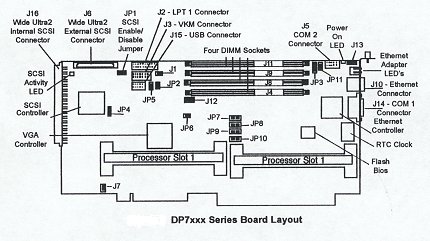
Jumpers JP6, 7, 8, 9 & 10 are processor dependent, and should not be changed from the factory settings.
Processor Termination
If only a single Pentium Processor is installed on the DP 7400/7500 board, a special termination card must be installed in the empty processor slot.
LEDs
Ethernet Adapter LED's
|
Near the RJ-45 connector and visible in
the mounting bracket are two sets of light emitting diodes (LEDs). On the upper set:
On the lower set:
|
SCSI Activity LED
There is an LED located between the internal and external SCSI connector which will be amber when the SCSI is busy.
Power LED
These is a Board Power LED between the COM2 and Fan Connector. This
LED will be green when there is power to the board.
Table 4-1, Memory Map
Memory Range |
Size |
Use |
| 00000-9FFFF | 640KB | Conventional Memory |
| A0000-AFFFF | 64KB | VGA Graphics Buffer |
| B0000-B7FFF | 32KB | MDA Text Buffer |
| B8000-BFFFF | 32KB | VGA/CGA Text Buffer |
| C0000-C7FFF | 32KB | VGA Bios |
| C8000-DFFFF | 96KB | Available |
| E0000-FFFFF | 127KB | System & PCI BIOS |
Table 4-2, I/O Map
| ISA Ports | Description |
| 0000-00FF | Various "AT" functions in ISP chip and keyboard controller |
| 01F0-01F7 | IDE hard drive interface |
| 02F8-02FF | COM2 |
| 03A0 | Cubix supervisory interface |
| 03A8-03AF | IES serial port |
| 03B4-03B5 | VGA |
| 03BC-03BF | LPT1 |
| 03C0-03CF | VGA |
| 03D4-03D5 | VGA |
| 03F0-03F7 | Floppy / IDE |
| 03F8-03FF | COM1 |
System Interrupts
The 16 system hardware interrupts on the SP are represented in Table 4 - 4. Interrupts are managed by two standard 8259A Programmable Interrupt Controllers (PICs). Interrupts at IRQ 0 through 7 are located on the main PIC; IRQ 8 through 15 are on the SLAVE PIC.
Table 4-3, System Interrupts
IRQ |
Description |
IRQ |
Description |
0 |
Timer clock | 8 |
Real Time Clock |
1 |
Keyboard | 9 |
Redirected IRQ 2 |
2 |
Second OIC controller | 10 |
Set By PCI Plug & Play at boot time |
3 |
COM2 | 11 |
Set By PCI Plug & Play at boot time |
4 |
COM1 | 12 |
Available (or PS/2 Mouse) |
5 |
Set By PCI Plug & Play at boot time | 13 |
Math Coprocessor |
6 |
Floppy Disk Controller | 14 |
Primary IDE Controller |
7 |
LPT1 | 15 |
Secondary IDE Controller (or IES) |
Systems | Circuit Boards | Other Products | Software | Hardware Identifier
Other Vendors | Technical Notes | Downloads | Search | Support Home Page
This document, and all
Web Site contents, Copyright ©
2000 by Cubix Corp., Carson City, NV, USA.