QL 3222
Chapter 9 - Hardware Reference
QL 3222 Specifications
Communication Processor
| Processor type and speed | Cx486SLC 33 MHZ |
| 80386SX 33 MHZ | |
| Coprocessor | (factory installed, optional) Cyrix Cx87SLC |
| Number per board | 2 |
| Hardware integer multiplier unit | |
| ... Cx486SLC | Internal |
| ... 80386SX | None |
| Internal cache size | |
| .. Cx486SLC | 1 Kbyte |
| .. 80386SX | None |
Communications Memory Support
| Total per processor | 4, 8, or 16 Mbytes |
| Conventional memory | 640 Kbytes [00000-9FFFF] |
| High memory | 384 Kbytes [A0000-FFFFF] |
| Extended memory | 1-15 Mbytes [100000-FFFFFF] |
| Memory type | PS/2 style, 72-pin SIMMs |
| Number of SIMM sockets per processor | 1 |
| Access time (RAM speed) | 70 nanoseconds |
| System and video BIOS ROM shadowing | Enabled |
Communications Video Support
| Video controller | Cirrus GD5428 |
| Video controller location | On-board |
| Modes supported (vertical x horizontal x color) | |
| ... 11 Hexadecimal | 640x480x2 |
| ... 12 Hexadecimal | 640x480x16 |
| ... 13 Hexadecimal | 320x200x256 |
| ... 58 Hexadecimal | 800x600x16 |
| ... 5C Hexadecimal | 800x600x256 |
| ... 5D Hexadecimal | 1024x768x16 |
| ... 5F Hexadecimal | 640x480x256 |
Communications Ports
| Serial (per processor) | |
| Assignment | COM1, COM2 |
| UART type | 16C550 |
| Buffering | 16 byte, FIFO |
| Maximum transmission rate | 115.2 Kbps |
| Connector type | |
| .. COM1 | DB-9 male on rear bracket |
| .. COM2 | Header to DB-9 male |
| Parallel (per processor) | |
| Assignment | LPT1 |
| Connector type | Header to DB-25 female |
Other Input/Output (per processor)
| IDE hard disk drive | Header to 44-pin ribbon cable |
| Mouse | Header to PS/2-style Mini-DIN 6 |
| Video | Header to DB-15 HD |
| Keyboard | Header to PS/2-style Mini-DIN 6 |
Network Characteristics
| Network interface | Built-in, ISA bus-based |
| Burst rate | 1 Mbytes/second or 8 Mbps |
Standards Support and Third Party Applications
| Novell NetWare® 3.11, 3.12, and 4.0 | Yes |
| Co-exist with Ethernet®, ARCnet® & IBM Token Ring® | Yes |
| MS-DOS® 5.x, 6.x and DR-DOS® 6.x | Yes |
| IBM OS/2 v 2.x | Yes |
| Microsoft Windows® 3.x | Yes |
| Dial-out interrupts 14 and 6B | Yes |
Utilities
| QLVision | |
| Across LAN processor monitoring | Yes |
| Across LAN processor hard reset | Yes |
| Across LAN screen/keyboard redirection | |
| .. Text based | Yes |
| .. Graphics based | No |
| Historical activity logs | Yes |
| ... Connection time and date | Yes |
| ... Connection duration | Yes |
| ... User identification | Yes |
| ... File, screen, and hard copy output | Yes |
| Diagnostic packet analysis | Yes |
| CPR monitoring | Yes |
| ... Automatic response to lockup | Reset |
| ... Interval of checking for lockup | 1-15 minutes |
Communications Processor Characteristics
| Configurable automatic reset | Upon loss of DCD/DSR |
| Line busy | Integrated |
| Diagnostic LEDs | Rear bracket |
Power
| Processor type Cx486SLC | |
| Rating (with coprocessor) | 20.4 watts |
| Rating (without coprocessor) | 19.4 watts |
| Requirements | |
| +5 VDC (with coprocessor) | 3.7 amps maximum |
| +5 VDC (without coprocessor) | 3.5 amps maximum |
| +12 VDC | 0.08 amps maximum |
| -12 VDC | 0.08 amps maximum |
| Processor type 80386SX | |
| Rating (with coprocessor) | 19.9 watts |
| Rating (without coprocessor) | 18.9 watts |
| Requirements | |
| +5 VDC (with coprocessor) | 3.6 amps maximum |
| +5 VDC (without coprocessor) | 3.4 amps maximum |
| +12 VDC | 0.08 amps maximum |
| -12 VDC | 0.08 amps maximum |
Environmental
| Operating temperature | 0 - 40 C |
| Relative humidity | 10 - 95% noncondensing |
| FCC Compliance | Class A |
Warranty
| Parts and labor return-to-manufacturer | 1 year |
QL 3222 I/O Connections
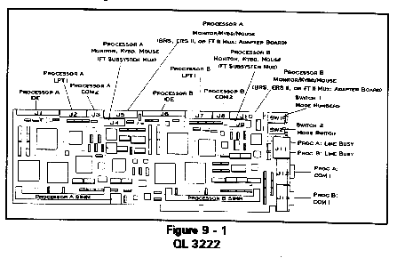
Connection of the I/O on the QL workstations varies with the enclosure in which the board is installed. The headers and connectors on the QL Series board should be connected to the device indicated for the appropriate enclosure in Table 9 - 1.
Table 9 - 1
QL 3222 I/O Connections
Header/ Connector |
Connector Description |
Connect to: |
*J1 44-pin header |
Processor A IDE hard drive |
2.5" IDE drive with 2mm pitch pins |
J2 20-pin header |
Processor A Parallel port (LPT1) |
Optional LPT1 adapter board |
J3 10-pin header |
Processor A Serial port (COM2) |
Optional COM2 adapter board |
J4 14-pin header |
Processor A Subsystem Mux |
Refer to Table 9 - 2 |
J5 26-pin header |
Processor A Monitor, keyboard, and mouse |
Refer to Table 9 - 2 |
*J6 44-pin header |
Processor B IDE hard drive |
2.5" IDE drive with 2mm pitch pins |
J7 20-pin header |
Processor B Parallel port (LPT1) |
Optional LPT1 adapter board |
J8 10-pin header |
Processor B Serial port (COM2) |
Optional COM2 adapter board |
J9 14-pin header |
Processor B Subsystem Mux |
Refer to Table 9 - 2 |
J10 26-pin header |
Processor B Monitor, keyboard, and mouse |
Refer to Table 9 - 2 |
J11 2 RJ-11 connectors |
Line busy connectors for both processors |
Telephone cable |
J12 DB-9 connector |
Processor A COM1 |
Serial device |
J15 DB-9 connector |
Processor B COM1 |
Serial device |
| * Cubix provides an optional 44-pin to 40-pin
plus power connector kit to enable the use of 3.5" IDE hard drives. Refer to Figure 9 - 1 for header and connector locations. |
||
Table 9 - 2
QL 3222 Monitor, Keyboard & Mouse Connectors
QL 3222 Installed In: |
J4 & J9 14-pin Header |
J5 & J10 26-pin Header |
Non-Cubix PC |
N/A |
Optional monitor, keyboard, and mouse adapter board |
Cubix BOS |
N/A |
Mux or optional monitor, keyboard, and mouse adapter board |
Cubix ERS |
N/A* |
Optional monitor, keyboard, and mouse adapter board |
Cubix ERS II |
N/A |
Mux or optional monitor, keyboard, and mouse adapter board |
Cubix ERS/FT |
Unused mux monitor, keyboard, and mouse channel |
Optional monitor, keyboard, and mouse adapter board |
Cubix ERS/FT II |
N/A |
Mux or optional monitor, keyboard, and mouse adapter board |
Cubix MultiServ/FT |
Unused mux monitor, keyboard, and mouse channel |
Optional monitor, keyboard, and mouse adapter board |
| * Do not connect the 14-pin J4 or J9 headers to the 14-pin connector on the Cubix ERS subsystem multiplexor. | ||
QL 4222 Specifications
Communication Processor
| Processor type and speed | 80486DX4 100 MHZ |
| 80486DX2 50 MHZ | |
| Number per board | 2 |
| Co-processor | Included |
| Hardware integer multiplier unit | Internal |
| Internal cache size | |
| ... 80486DX4 | 16 Kbytes |
| ... 80486DX2 | 8 Kbytes |
Communications Memory Support
| Total per processor | 4, 8, 16, 32, or 64 Mbytes |
| Conventional memory | 640 Kbytes [00000-9FFFF] |
| High memory | 384 Kbytes [A0000-FFFFF] |
| Extended memory | 1-63 Mbytes [100000-3FFFFFF] |
| Memory type | PS/2 style, 72-pin SIMMs |
| Number of SIMM sockets per processor | 1 |
| Access time (RAM speed) | 70 nanoseconds |
| System and video BIOS ROM shadowing | Enabled |
Communications Video Support
| Video controller | Cirrus GD5428 |
| Video controller location | On-board |
| Modes supported (vertical x horizontal x color) | |
| 11 Hexadecimal | 640x480x2 |
| 12 Hexadecimal | 640x480x16 |
| 13 Hexadecimal | 320x200x256 |
| 58 Hexadecimal | 800x600x16 |
| 5C Hexadecimal | 800x600x256 |
| 5D Hexadecimal | 1024x768x16 |
| 5F Hexadecimal | 640x480x256 |
| 60 Hexadecimal | 1024x768x256 |
| 62 Hexadecimal | 640x480x32768 |
| 63 Hexadecimal | 800x600x32768 |
| 64 Hexadecimal | 640x480x65536 |
| 65 Hexadecimal | 800x600x65536 |
| 66 Hexadecimal | 640x480x32768 |
| 67 Hexadecimal | 800x600x32768 |
| 6C Hexadecimal | 1280x1024x16 |
| 71 Hexadecimal | 640x480x16,800,000 |
Communications Ports
| Serial (per processor) | |
| Assignment | COM1, COM2 |
| UART type | 16C550 |
| Buffering | 16 byte, FIFO |
| Maximum transmission rate | 115.2 Kbps |
| Connector type | |
| ... COM1 | DB-9 male on rear bracket |
| ... COM2 | Header to DB-9 male |
| Parallel (per processor) | |
| Assignment | LPT1 |
| Connector type | Header to DB-25 female |
Other Input/Output (per processor)
| IDE hard disk drive | Header to 44-pin ribbon cable |
| Floppy disk drive | Header to 34-pin ribbon cable |
| Mouse | Header to PS/2-style Mini-DIN 6 |
| Video | Header to DB-15 HD |
| Keyboard | Header to PS/2-style Mini-DIN 6 |
Network Characteristics
| Network interface | Built-in, ISA bus-based |
| Burst rate | 4 Mbytes/second or 32 Mbps |
Standards Support and Third Party Applications
| Novell NetWare® 3.11, 3.12, and 4.0 | Yes |
| Co-exist with Ethernet®, ARCnet® & IBM Token Ring® | Yes |
| MS-DOS® 5.x, 6.x and DR-DOS® 6.x | Yes |
| IBM OS/2 v 2.x | Yes |
| Microsoft Windows® 3.x | Yes |
| Dial-out interrupts 14 and 6B | Yes |
Utilities
| QLVision | |
| Across LAN processor monitoring | Yes |
| Across LAN processor hard reset | Yes |
| Across LAN screen/keyboard redirection | |
| .. Text based | Yes |
| .. Graphics based | No |
| Historical activity logs | Yes |
| ... Connection time and date | Yes |
| ... Connection duration | Yes |
| ... User identification | Yes |
| ... File, screen, and hard copy output | Yes |
| Diagnostic packet analysis | Yes |
| CPR monitoring | Yes |
| ... Automatic response to lockup | Reset |
| ... Interval of checking for lockup | 1-15 minutes |
Communications Processor Characteristics
| Configurable automatic reset | Upon loss of DCD/DSR |
| Line busy | Integrated |
| Diagnostic LEDs | Rear bracket |
Power
| Processor type 80486DX4 | |
| Rating | 30.4 watts |
| Requirements | |
| +5 VDC | 5.7 amps maximum |
| +12 VDC | 0.08 amps maximum |
| -12 VDC | 0.08 amps maximum |
| Processor type 80486DX2 | |
| Rating | 23.4 watts |
| Requirements | |
| +5 VDC | 4.3 amps maximum |
| +12 VDC | 0.08 amps maximum |
| -12 VDC | 0.08 amps maximum |
Environmental
| Operating temperature | 0 - 40 C |
| Relative humidity | 10 - 95% noncondensing |
| FCC Compliance | Class A |
Warranty
| Parts and labor return-to-manufacturer | 1 year |
QL 4222 I/O Connections
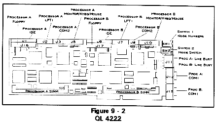
Connection of the I/O on the QL workstations varies with the enclosure in which the board is installed. The headers and connectors on the QL Series board should be connected to the device indicated for the appropriate enclosure in Table 9 - 3.
Table 9 - 3
QL 4222 I/O Connections
Header/ Connector |
Connector Description |
Connect to: |
*J1 44-pin header |
Processor A IDE hard drive |
2.5" IDE drive with 2mm pitch pins |
J2 20-pin header |
Processor A Parallel port (LPT1) |
Optional LPT1 adapter board |
J3 10-pin header |
Processor A Serial port (COM2) |
Optional COM2 adapter board |
J5 26-pin header |
Processor A Monitor, keyboard, and mouse |
Refer to Table 9 - 4. |
*J6 44-pin header |
Processor B IDE hard drive |
2.5" IDE drive with 2mm pitch pins |
J7 20-pin header |
Processor B Parallel port (LPT1) |
Optional LPT1 adapter board |
J8 10-pin header |
Processor B Serial port (COM2) |
Optional COM2 adapter board |
J10 26-pin header |
Processor B Monitor, keyboard, and mouse |
Refer to Table 9 - 4 |
J11 2 RJ-11 connectors |
Line busy connectors for both processors |
Telephone cable |
J12 DB-9 connector |
Processor A COM1 |
Serial device |
J15 DB-9 connector |
Processor B COM1 |
Serial device |
J16 34-pin header |
Processor A Floppy drive |
3.5" or 5.25" floppy drive |
J17 34-pin header |
Processor B Floppy drive |
3.5" or 5.25" floppy drive |
| * Cubix provides an optional 44-pin to 40-pin
plus power connector kit to enable the use of 3.5" IDE hard drives. Refer to Figure 9 - 2 for header and connector locations. |
||
Table 9 - 4
QL 4222 Monitor, Keyboard & Mouse Connectors
QL 3222 Installed In: |
J5 & J10 26-pin Header |
Non-Cubix PC |
Optional monitor, keyboard, and mouse adapter board |
Cubix BOS |
Mux or optional monitor, keyboard, and mouse adapter board |
Cubix ERS |
Optional monitor, keyboard, and mouse adapter board |
Cubix ERS II |
Mux or optional monitor, keyboard, and mouse adapter board |
Cubix ERS/FT |
Optional monitor, keyboard, and mouse adapter board |
Cubix ERS/FT II |
Mux or optional monitor, keyboard, and mouse adapter board |
Cubix MultiServ/FT |
Optional monitor, keyboard, and mouse adapter board |
Optional Connectors
In addition to the connectors available from the end bracket of the QL board, additional connectors may be installed for the QL workstations.
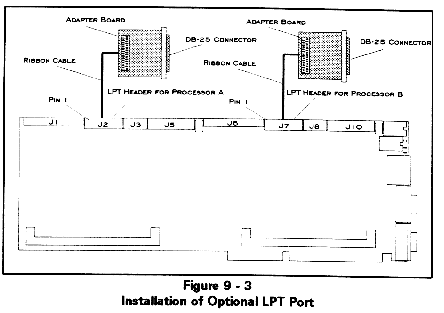
Because each QL board contains two complete workstations, and due to the limited space on the end bracket of an AT-style board, Cubix makes these optional connectors available by providing the signals required for each connector via a header on the top of the board. Cubix also supplies breakout kits which convert the signals on these headers to standard connectors. Each breakout kit contains an adapter board with the standard connector on one end and a connector on the other end which attaches via a cable to the header on the QL board. Figure 9 - 3 illustrates the concept of adding optional parallel printer port connectors (LPT ports) to both workstations on a QL Series board. The available breakout kits include:
If there are empty slots in the system containing the QL boards, the standard connector on the adapter board may be installed in the end bracket space for this slot. A bracket is provided for this purpose.
If no slots are available and the QL board is installed in a Cubix subsystem, the standard connector on the adapter board may be installed using an auxiliary junction panel as described in the subsystem documentation.
Regardless of where the adapter board will be located, the installation procedures are the same. Refer to Figures 9 - 1 and 9 - 2 to determine the location of the header required to connect any desired optional connectors. Then follow the optional connector installation instructions in the next section.
Installation Instructions
Warning!!
Turn off power to the system before beginning this procedure.
Table 9-5
Optional Connector Headers
Connectors |
Processor A Header |
Processor B Header |
LPT |
J2 |
J7 |
Monitor, Keyboard, & Mouse |
J5* |
J10* |
COM2 |
J3 |
J8 |
3.5" IDE Drive |
J1 |
J6 |
| * The QL 3222 has the monitor, keyboard, and mouse signals brought to two headers per workstation. In addition to the 26-pin J5 and J10 headers, the 14-pin J4 and J9 headers also provide these signals. The new breakout kits will accommodate either header (using the 26-pin header is recommended). The older-style kits only use the 14-pin headers. | ||
Connectors and Cables
Parallel Port Connectors
This header requires a optional I/O adapter from Cubix. Attempting to connect a device directly to this connector will damage the board.
Serial Port Connector
Table 9-8
COM1 and Optional COM2 DB-9 Connectors
| 1 DCD (data carrier detect) | 2 RD (receive data) |
| 3 TD (transmit data) | 4 DTR (data terminal ready) |
| 5 GND (ground) | 6 DSR (data set ready) |
| 7 RTS (request to send) | 8 CTS (clear to send) |
| 9 RI (ring indicator) |
Serial Port Cables
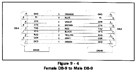
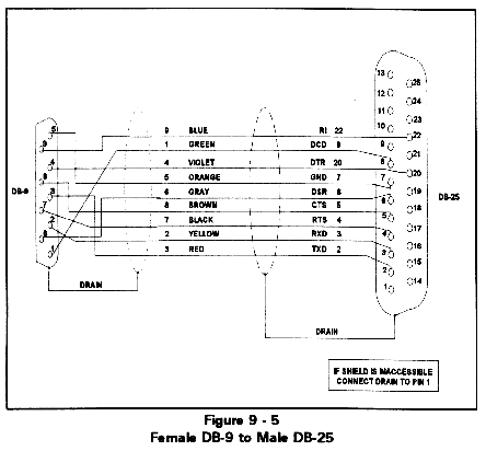
Each QL workstation is equipped with a standard PC/AT-type COM1 port accessible via a DB-9 male connector on the end bracket of the board. Typically this port is connected to a DB-9 or DB-25 port on a modem. The cables required for this type of connection are illustrated in Figures 9 - 4 and 9 - 5 and may be acquired from Cubix.
IDE Hard Disk Drive Connector
Figure 9-9
IDE Interface Connector (44 pin header)
| 1 ground | 2 speed | 3 ground |
| 4 n/c | 5 ground | 6 n/c |
| 7 ground | 8 index | 9 ground |
| 10 motor on | 11 ground | 12 drive sel 2 |
| 13 ground | 14 motor sel 1 | 15 ground |
| 16 motor on 2 | 17 ground | 18 direction |
| 19 ground | 20 stop step | 21 ground |
| 22 write data | 23 ground | 24 write gate |
| 25 ground | 26 track 0 | 27 ground |
| 28 write protect | 29 ground | 30 read data |
| 31 ground | 32 side select | 33 ground |
| 34 disk change |
Floppy Drive Connector (QL 4222 Only)
Figure 9-10
Floppy Drive Interface Connector (34 pin header)
| 1 ground | 2 speed | 3 ground |
| 4 n/c | 5 ground | 6 n/c |
| 7 ground | 8 index | 9 ground |
| 10 motor on | 11 ground | 12 drive sel 2 |
| 13 ground | 14 motor sel 1 | 15 ground |
| 16 motor on 2 | 17 ground | 18 direction |
| 19 ground | 20 stop step | 21 ground |
| 22 write data | 23 ground | 24 write gate |
| 25 ground | 26 track 0 | 27 ground |
| 28 write protect | 29 ground | 30 read data |
| 31 ground | 32 side select | 33 ground |
| 34 disk change |
Line Busy Cable
Optional Hard Disk Drive
An IDE hard drive interface is included on the QL board for applications that require a hard disk drive. IDE drives include an AT compatible disk controller. The hard disk controller uses IRQ 14 for its interrupt. The IDE interface will support one or two 2.5" IDE mini drives, connected via the internal 44-pin ribbon cable. Cubix also provides an optional 44-pin to 40-pin plus power connector kit to enable use of 3.5" IDE drives.
Installing an IDE hard drive requires modifying the BIOS Setup. Refer to the BIOS Setup section later in this chapter.
Note: A QL with a hard disk drive configured but not attached will experience a significant increase in boot time due to disk access timeouts.
Mini Drive (2.5") Installation
Attach one end of the cable to the disk drive(s) and the other end directly to the IDE header on the top of the QL board. In addition to the standard disk data signals, power is also provided to the mini drives via this header. There are two IDE headers (J1 and J2), one for each QL workstation on the board (refer to Figures 9 - 1 and 9 - 2 for header locations).
3.5" Drive Installation
To support 3.5" IDE hard disk drives, a 3.5" Adapter and Cable Kit must be installed as explained in the Optional Connectors section of this chapter. This kit converts the 44-pin header on the QL to a 40-pin connector on the adapter board. The 3.5" IDE drive then attaches to the 40-pin header on the adapter board. Power must be provided to the 3.5" drive from a separate power source. No power is provided via the adapter board connector.
Operating System Installation
The hard drive must be configured with an operating system. Instructions for installing DOS and OS/2 are provided in the following sections.
DOS
Cubix configures DOS formatted disk drives for the QL Series products with all of the files necessary for the QL processor to boot as a NetWare workstation.
Only the QL 4222 member of the QL Series of products supports a floppy disk drive. If it is necessary to install a hard disk drive that has not been configured by Cubix onto a model of QL other than the QL 4222, the lack of a floppy interface necessitates that one of the following methods for configuring the hard drive for local boot be employed. Note that before configuring the drive it must first be formatted as a bootable DOS disk.
OS/2
Cubix configures OS/2 formatted disk drives for the QL Series products with all of the files necessary for the QL processor to boot as a NetWare workstation. If it is necessary to install a disk drive that has not been configured by Cubix, follow the instructions below..
To install the Cubix QL OS/2 ODI Workstation Drivers and Cubix OS/2 Mouse Driver on a hard drive, the following is needed:
Procedure
Note: If the hard drive is for a QL 4222, this instruction refers to the QL workstation.
A:INSTALL
Target: C:\NETWARE
Source: A
If the IDE drive being configured is installed as drive C: and the OS/2 Installation Utility Diskette is in drive A:, select OK. Otherwise, correct the drive information.
QL4_OS2.SYS if the drive is to be connected to a QL 4001, or QL3_OS2.SYS if the drive is to be connected to a QL 3222
Then select Continue.
IPX Support for DOS and Windows ON
Also select:
Global NetWare Shell Support
Then select Continue.
Save file as C:\CONFIG.SYS
If this information is correct, select OK.
Default ODI LAN Driver: QL4_OS2.SYS (or QL3_OS2.SYS)
Select Copy only the default driver. Then select OK.
Requester will copy files to C:\NETWARE
If this information is correct, select Copy.
copy a:net.ql4 net.cfg
If the drive is to be connected to a QL 3222, type
copy a:net.ql3 net.cfg
copy a:cbxmouse.sys os2
This will copy the file to the C:\OS2\ subdirectory.
e config.sys
This will invoke the OS/2 text editor.
device=c:\mouse.sys
Replace this line with the following line:
device=c:\os2\cbxmouse.sys
C:\NETWARE\QL4_OS2.SYS (or QL3_OS2.SYS)
C:\OS2\CBXMOUSE.SYS
C:\NET.CFG
Type Exit to close the OS/2 session. Shut down the OS/2 operating system (this can be done by either clicking the right mouse button while pointing to the grey background space and then selecting Shut Down, or, if a mouse is not available, press <CTRL>\ followed by <CTRL> F10 and select Shut Down).
Verification
After installation of the Cubix QL OS/2 driver, the hard drive will only boot when attached to the QL processor. If the hard drive is not already connected to the QL processor, connect it at this time. Note that this requires placing the drive in the NetWare server or router that contains the QL The server or router must have Cubix QL Series Software v5.00 or higher installed to support these OS/2 Workstation drivers.
To verify correct installation of the driver, boot the QL board with the hard disk attached by loading the QL server driver on the device where the board is located. If the OS/2 operating system comes up completely (to the Presentation Manager Desktop) without any errors, the driver is installed correctly.
To verify correct installation of the Cubix OS/2 Mouse Driver, boot the QL board with the OS/2 hard drive attached and no mouse connected. If the QL processors displays a mouse pointer on the screen, the mouse driver is installed correctly.
Optional Floppy Disk Drive
A floppy drive interface is included on the QL 4222 board to support installation of applications from a floppy disk onto the local QL 4222 hard disk drive. The floppy interface will support up to two 3.5" or 5.25" drives, connected via a standard 34-pin ribbon cable. One end of the cable attaches to the disk drive(s) and the other end connects directly to the floppy drive header on the top of the QL 4222 board. There are two floppy drive headers (J16 and J17), one for each QL workstation on the board (refer to Figure 9 - 2 for header locations). The floppy disk controller uses IRQ 6 and DMA channel 2.
Installing a floppy disk drive requires modifying the BIOS Setup. Refer to the BIOS Setup section later in this chapter. Since the QL 4222 has no battery to maintain the CMOS configuration, the BIOS must be reconfigured every time power is cycled to the QL board if floppy drive support is desired.
Notice! The QL4222 may boot from a floppy disk only if a hard disk drive is also connected to the QL workstation.
Floppy disk drive support is not available on the QL 3222.
Note: A QL with a floppy disk drive configured but not attached will experience a significant increase in boot time due to disk access timeouts.
BIOS Setup
The QL products have an American Megatrends, Inc. (AMI) system BIOS setup and hard disk setup embedded in EPROM for each processor on the board. This BIOS has been configured specifically for the QL. It is recommended that no changes be made to the BIOS setup configuration except to add disk drive support.
Changes to the BIOS setup configuration are stored in CMOS memory that is not battery powered. Therefore the QL BIOS will return to its original state upon power failure. However, special support for the optional QL hard disk drive has been incorporated to preserve the hard disk drive configuration through loss of power. No support to maintain the floppy disk drive configuration through a power fail is included.
Modifying the Configuration
A monitor and keyboard must be directly connected to the QL to modify the BIOS configuration. To invoke the BIOS setup utility:
Once in setup, select:
STANDARD CMOS SETUP
by pressing <ENTER>.
The disk configuration will be displayed.
Hard Drive Configuration
On a QL 3222, use the arrow keys to position the cursor on the Hard disk C: type field. On a QL 4222, select the Master Disk. Use the <PgUp> and <PgDn> keys to select the desired disk drive type (Table 9 - 11 lists these options), or automatically configure the disk drive parameters as follows:
Floppy Drive Configuration
Floppy drive support is incorporated only on the QL 4222. Use the arrow keys to select Floppy Drive A: or Floppy Drive B:. Use the <PgUp> and <PgDn> keys to select the correct floppy type (i.e. 1.2 Mbyte 5.25", 1.44 Mbyte 3.5", etc.).
Saving the Configuration
After completing the disk drive configuration, press <ESC>. Select:
WRITE TO CMOS AND EXIT
from the menu. The QL will reboot with the new BIOS configuration.
Notice!
When configuring disk drive support on QL workstations, be aware of the following:
Table 9 - 11
Hard Disk Configuration
| Type | Cyls | Heads | WPcom | CtrlByte | LZone | Secs | Size |
| 1 | 306 | 4 | 128 | 0 | 305 | 17 | 10 MB |
| 2 | 615 | 4 | 300 | 0 | 615 | 17 | 20 MB |
| 3 | 615 | 6 | 300 | 0 | 615 | 17 | 31 MB |
| 4 | 940 | 8 | 512 | 0 | 940 | 17 | 62 MB |
| 5 | 940 | 6 | 512 | 0 | 940 | 17 | 47 MB |
| 6 | 615 | 4 | 65535 | 0 | 615 | 17 | 20 MB |
| 7 | 462 | 8 | 256 | 0 | 511 | 17 | 31 MB |
| 8 | 733 | 5 | 65535 | 0 | 733 | 17 | 30 MB |
| 9 | 900 | 15 | 65535 | 8 | 901 | 17 | 112 MB |
| 10 | 820 | 3 | 65535 | 0 | 820 | 17 | 20 MB |
| 11 | 855 | 5 | 65535 | 0 | 855 | 17 | 35 MB |
| 12 | 855 | 7 | 65535 | 0 | 855 | 17 | 50 MB |
| 13 | 306 | 8 | 128 | 0 | 319 | 17 | 20 MB |
| 14 | 733 | 7 | 65535 | 0 | 733 | 17 | 43 MB |
| 15 | 0 | 0 | 0 | 0 | 0 | 0 | 0 MB |
| 16 | 612 | 4 | 0 | 0 | 663 | 17 | 20 MB |
| 17 | 977 | 5 | 300 | 0 | 977 | 17 | 41 MB |
| 18 | 977 | 7 | 65535 | 0 | 977 | 17 | 57 MB |
| 19 | 1024 | 7 | 512 | 0 | 1023 | 17 | 60 MB |
| 20 | 733 | 5 | 300 | 0 | 732 | 17 | 30 MB |
| 21 | 733 | 7 | 300 | 0 | 732 | 17 | 43 MB |
| 22 | 733 | 5 | 300 | 0 | 733 | 17 | 30 MB |
| 23 | 306 | 4 | 0 | 0 | 336 | 17 | 10 MB |
| 24 | 925 | 7 | 0 | 0 | 925 | 17 | 54 MB |
| 25 | 925 | 9 | 65535 | 8 | 925 | 17 | 69 MB |
| 26 | 754 | 7 | 754 | 0 | 754 | 17 | 44 MB |
| 27 | 754 | 11 | 65535 | 8 | 754 | 17 | 69 MB |
| 28 | 699 | 7 | 256 | 0 | 699 | 17 | 41 MB |
| 29 | 823 | 10 | 65535 | 8 | 823 | 17 | 68 MB |
| 30 | 918 | 7 | 918 | 0 | 918 | 17 | 53 MB |
| 31 | 1024 | 11 | 65535 | 8 | 1024 | 17 | 94 MB |
| 32 | 1024 | 15 | 65535 | 8 | 1024 | 17 | 128 MB |
| 33 | 1024 | 5 | 1024 | 0 | 1024 | 17 | 43 MB |
| 34 | 612 | 2 | 128 | 0 | 612 | 17 | 10 MB |
| 35 | 1024 | 9 | 65535 | 8 | 1024 | 17 | 77 MB |
| 36 | 1024 | 8 | 512 | 0 | 1024 | 17 | 68 MB |
| 37 | 615 | 8 | 128 | 0 | 615 | 17 | 41 MB |
| 38 | 987 | 3 | 987 | 0 | 987 | 17 | 25 MB |
| 39 | 987 | 7 | 987 | 0 | 987 | 17 | 57 MB |
| 40 | 820 | 6 | 820 | 0 | 820 | 17 | 41 MB |
| 41 | 977 | 5 | 977 | 0 | 977 | 17 | 41 MB |
| 42 | 981 | 5 | 981 | 0 | 981 | 17 | 41 MB |
| 43 | 830 | 7 | 512 | 0 | 830 | 17 | 48 MB |
| 44 | 830 | 10 | 65535 | 8 | 830 | 17 | 69 MB |
| 45 | 917 | 15 | 65535 | 8 | 918 | 17 | 114 MB |
| 46 | 1224 | 15 | 65535 | 8 | 1223 | 17 | 152 MB |
| 47 | User Configurable | ||||||
To configure a disk drive that does not have the settings specified in types 1-46, select type 47. Then enter the appropriate values for the number of Cylinders, Heads, WPcom, LZone, and Sectors.
Local Boot Process
The QL interfaces with the IDE drive at system boot as follows:
1. The QL checks for the existence of a C: drive. If one is found, the QL checks for a D: drive. If no C: drive is found, the QL will not attempt to locate a D: drive.
2. The CMOS disk drive configuration is verified. If it is not correct, the QL updates the CMOS configuration and reboots.
3. The user is given the option to boot from a network drive. If the user does not respond after two seconds, the QL boots from the local drive. If an A: drive is present and a floppy disk is installed, the QL will attempt to boot from the floppy disk. Otherwise, the QL will attempt to boot from a B: drive if a disk is present. If neither an A: nor a B: drive is configured with a floppy disk installed, the QL will boot from the C: drive.
Messages
Do you want to boot from the network? (Y/N)
This message is displayed when at least one hard drive exists and all hard drives have already been set up correctly. The user has 2 seconds to respond to the question. If the user does not respond, "NO" is assumed. Answering "NO" will cause the QL to boot from a local drive. Answering "YES" will cause the QL to boot from an image file on the network.
setting up xxxx
This message occurs when the QL finds a drive that has not been configured. The "xxxx" refers to the model number string found and generally provides the manufacturer and model number of the drive. The message informs the user that a drive was found and that it is being initialized.
rebooting. . .
This message occurs after the drive(s) have been configured by the QL. The QL must be rebooted to allow the new drive parameters to take effect. This message informs the user that the QL is about to reboot. The message is displayed for 2 seconds.
no C: drive present
This message occurs when the QL does not detect any attached IDE hard drives. The QL will attempt to perform a remote boot from an image file on a file server.
Notes
Line Busy
The purpose of the line busy feature is to force a phone line connected to a QL workstation to appear busy until the QL is ready to answer a call. This prevents an incoming call from ringing a line that will not answer. The line busy feature should be used in conjunction with the feature to reset a QL processor on loss of DCD/DSR described in Chapter 2. When a dial-in session terminates (i.e. the user hangs up), DCD and/or DSR will drop and the QL will reset. The line busy feature is invoked as the workstation reboots, keeping the line busy until the communication application on the QL initializes.
Rotary PBX Systems
Typically a rotary system is connected to multiple QL workstations so that an incoming call will rotate through the lines searching for the first line not in use. This line will then ring. If the modem connected to this line is initializing, or if the QL workstation connected to this modem is booting, the line might never be answered. The line busy feature eliminates this condition by forcing the line to appear busy until the modem and the QL workstation are ready to answer an incoming call. Since the line is busy, the rotary system continues on to the next available line.
Operation
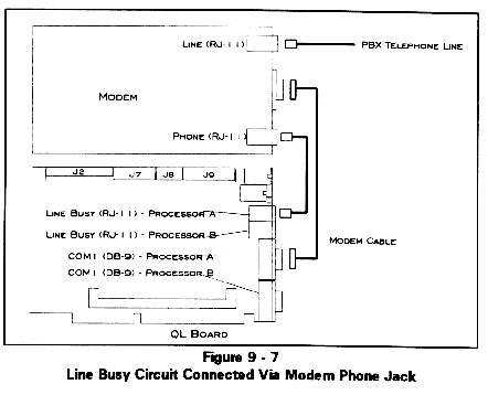
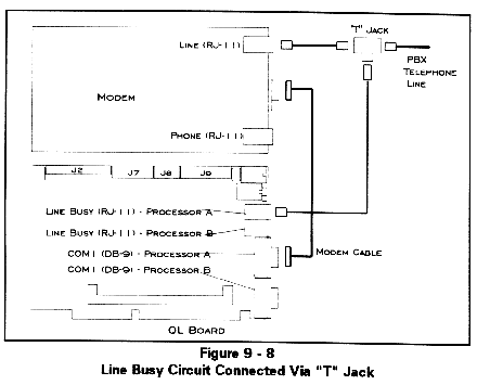
If the reset on loss of DCD/DSR option is enabled, the QL will experience a hardware reset when a dial-in session terminates. The QL workstations assert DTR false on a hardware reset operation. The line busy circuit uses the DTR signal from the QL workstation's COM1 port to determine whether or not the workstation is ready for a call. If DTR is false, the line busy circuit creates an off-hook condition on the telephone line. When DTR is asserted true, the line busy circuit will terminate the off-hook condition, and the QL workstation will respond to an incoming call. It is the responsibility of the communications application running on the workstation to assert the DTR signal true.
Installation Instructions
Note: Before enabling the line busy feature, verify that the reset on loss of DCD/DSR feature is configured as explained in the Installation chapter.
Troubleshooting
If the line busy circuit does not cause the line to appear busy when the QL workstation is ready to accept an incoming call, check the cable connections.
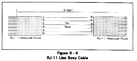
The center two pins of the RJ-11, tip and ring, should measure approximately 48 volts DC under on-hook conditions. When the line busy circuit has asserted an off-hook condition, the tip-ring voltage should be approximately 8 volts DC. Refer to Figure 9 - 6 in the Connectors and Cables section of this chapter to locate tip and ring.
If the line busy circuit is not asserting off-hook, check the state of the DTR signal. DTR is false when it is -6 volts with respect to ground. DTR is true when it is +6 volts with respect to ground. DTR can be measured on either end of the cable connecting COM1 to the modem. On a DB-9 connector, DTR is on pin 4 and ground is on pin 5; on a DB-25 connector, DTR is on pin 20 and ground is on pin 7.
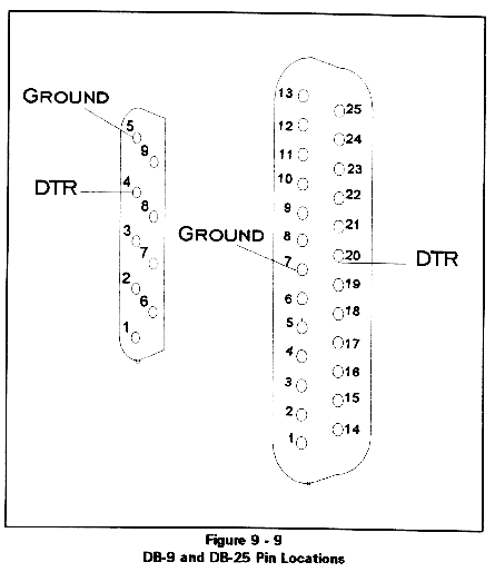
If DTR is not changing as expected, check the Cubix processor's COM1 port hardware. Verify the COM1 port configuration in the communication application software.
If DTR is changing properly and the telephone line is not changing from 48 volts to 8 volts, contact Cubix Customer Service for assistance.
Memory
The QL Series boards are equipped with a minimum of 4 Mbytes per processor. The memory is provided in one 72-pin by 36-bit standard 70ns SIMM module per processor. These SIMMs are defined in Table 9 - 12. Refer to Figures 9 - 1 and 9 - 2 to determine SIMM locations.
Table 9-12
SIMM Definitions
SIMM Type |
Banks |
Total Memory |
1M x 36 |
Single |
4MB |
2M x 36 |
Double |
8MB |
4M x 36 |
Single |
16MB |
8M x 36 |
Double |
32MB |
16M x 36 |
Single |
64MB |
Memory Map
The default QL memory configuration is 640 Kbytes of conventional memory and 256 Kbytes of Expanded (EMS) Memory, with all memory above 1 Mbyte configured as extended (XMS) memory. All memory above 1 Mbyte can be configured as Expanded or Extended memory.
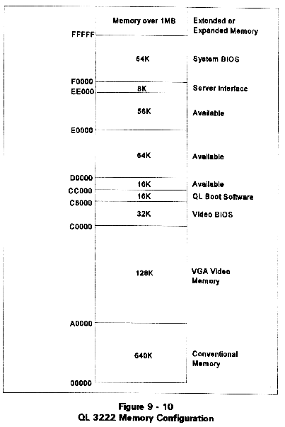
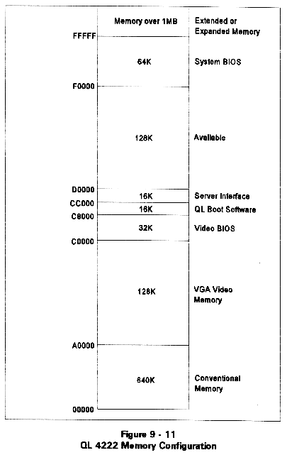
The areas of memory labeled as "Available" may be used by a memory manager to increase the amount of conventional memory available for applications.
The maps illustrated assumes a VGA or EGA configuration. If the application software to be run on the QL processor does not require VGA/EGA, additional memory becomes available as follows:
CGA: Uses B8000 to BFFFF.
A0000 to B7FFF is available.
Mono: Uses B0000 to B7FFF.
A0000 to AFFFF and B8000 to BFFFF are available.
Note: Be careful in assigning video memory for use by memory managers. If a VGA application is run on a QL processor which has reassigned video memory, that processor will fail.
QL I/O Map
| 000 - 00F | DMA 1 |
| 020 - 021 | PIC 1 |
| 040 - 043 | Timer |
| 060, 064 8742 | Keyboard controller |
| 061 | Port B |
| 070 - 071 | CMOS RAM & NMI mask register |
| 080 | Manufacturing HEX display |
| 081 - 08F | DMA Page registers |
| 0A0 - 0A1 | PIC 2 |
| 0C0 - 0DF | DMA 2 |
| 1F0 - 1F7 | IDE Hard disk drive |
| 2F8 - 2FF | COM2 |
| 300 - 302 | QL Command/Status |
| 378 - 37F | LPT1 |
| 3B0 - 3DF | VGA |
| 3F0 - 3F7 | Floppy drive (QL 4222 only) |
| 3F8 - 3FF | COM1 |
| 46E8,102 | VGA configuration ports |
Interrupt Channels
| NMI | Parity/VGA |
| 0 | Timer |
| 1 | Keyboard |
| 2 | Cascaded Input for PIC 2 |
| 3 | COM 2 |
| 4 | COM 1 |
| 5 | QL 3222: Interrupt from File Server QL 4222: Not Used |
| 6 | QL 3222: Interrupt from File Server QL 4222: Floppy Disk Drive |
| 7 | LPT 1 |
| 8 | Real Time Clock |
| 9 | VGA |
| 10 | Interrupt from File Server |
| 11 | Not Used |
| 12 | PS/2 Mouse Interrupt |
| 13 | Numeric Coprocessor Interrupt |
| 14 | IDE Hard Disk Drive |
| 15 | Not Used |
DMA Channels
QL 3222
No DMA channels are used by the QL 3222.
QL 4222
DMA channel 2 is used by the floppy disk controller on the QL 4222.
Diagnostic LEDs
Two green LEDs are located on the end bracket of the QL board above the Line Busy connectors (when the edge connector is pointing down). The top LED indicates the status of Processor A and the bottom LED indicates the status of Processor B.
Each LED is illuminated while the corresponding processor is in reset. After the processor boots, the LED will be turned on during data transfers between the QL workstation and the server or router in which the board is installed.
This document, and all Web contents, Copyright © 1997 by Cubix Corp., Carson City, NV, USA.