MM 2008
Quick Reference Guide
(From Cubix
Document 848A)
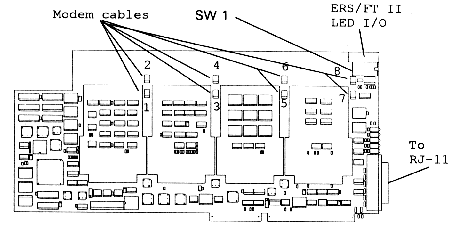
The Cubix MM package includes a cable that runs between the DB-25 D-connector on the MM 2008 and the Line Adapter module. The pin-outs for the DB-25 connections are as follows:
| 1 | Tip 1 | 14 | Ring 1 |
| 2 | Tip 2 | 15 | Ring 2 |
| 3 | Tip 3 | 16 | Ring 3 |
| 4 | Tip 4 | 17 | Ring 4 |
| 5 | Tip 5 | 18 | Ring 5 |
| 6 | Tip 6 | 19 | Ring 6 |
| 7 | Tip 7 | 20 | Ring 7 |
| 8 | Tip 8 | 21 | Ring 8 |
| 9 | Line Busy 1 | 22 | Line Busy 2 |
| 10 | Line Busy 3 | 23 | Line Busy 4 |
| 11 | Line Busy 5 | 24 | Line Busy 6 |
| 12 | Line Busy 7 | 25 | Line Busy 8 |
| 13 | Ground |
All MM Series adapter boards have a single switch bank labeled SW1 on the top edge of the adapter, near the end bracket (Figure 2.1). This switch bank consists of eight switches, numbered one through eight. These switches should only be changed while no power is applied to the MM adapter.
The switches in bank SW1 set the input/output (I/O) port address and the logical board number to be used by the MM adapter. Switches 1 and 2 control the I/O port address, while switches 4-8 control the logical board number. Switch 3 should always be ON.
The default switch settings for SW1 are all ON.

Base I/O Address Selection
The MM adapter boards require a series of 16 I/O locations to allow communications between the Cubix software driver and the hardware. Switches 1 and 2 of switch bank SW1 set the base I/O address to be used for this I/O address range. The MM boards support four different I/O address ranges (numbers given in hexadecimal):
Table 2 - 1, Base I/O Address Selection
Base I/O Address |
Range |
S-1 |
S-2 |
| 200 | 200-20F |
ON |
ON |
| 210 | 210-21F |
ON |
OFF |
| 300 | 300-30F |
OFF |
ON |
| 310 | 310-31F |
OFF |
OFF |
Select any base I/O address that does not conflict with other system hardware. Selecting a base I/O address other than the default may affect loading the software driver. Refer to Chapter 5 - WorldDesk Dial Installation for software installation details.
NOTE! - ALL MM SERIES ADAPTER BOARDS IN THE SYSTEM MUST USE THE SAME BASE I/O ADDRESS. Further, I/O addresses used by the MM adapter board must not conflict with the I/O addresses in use by any other system hardware.
Logical Board Number Selection
Each MM Series adapter installed in a server must be assigned a unique logical board number. The logical board number is used (along with a port number) to identify individual ports when the software driver is loaded. If two MM Series adapters attempt to use the same logical board number, driver failure will result.
Any board number from one to fourteen may be selected for use by a board. Assign board numbers sequentially, beginning with board number one. Switch bank SW1 switches 4-8 are used to set the board number for the hardware. The MM Series software dynamically detects the assigned board numbers. The switch settings for the logical board numbers are listed in Table 2-2.
Table 2 - 2, Board Number Selection
Logical Board |
S-4 |
S-5 |
S-6 |
S-7 |
S-8 |
| default 1 | ON |
ON |
ON |
ON |
OFF |
| 2 | ON |
ON |
ON |
OFF |
ON |
| 3 | ON |
ON |
ON |
OFF |
OFF |
| 4 | ON |
ON |
OFF |
ON |
ON |
| 5 | ON |
ON |
OFF |
ON |
OFF |
| 6 | ON |
ON |
OFF |
OFF |
ON |
| 7 | ON |
ON |
OFF |
OFF |
OFF |
| 8 | ON |
OFF |
ON |
ON |
ON |
| 9 | ON |
OFF |
ON |
ON |
OFF |
| 10 | ON |
OFF |
ON |
OFF |
ON |
| 11 | ON |
OFF |
ON |
OFF |
OFF |
| 12 | ON |
OFF |
OFF |
ON |
ON |
| 13 | ON |
OFF |
OFF |
ON |
OFF |
| 14 | ON |
OFF |
OFF |
OFF |
ON |
| 15 | ON | OFF | OFF | OFF | OFF |
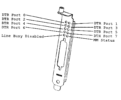
LEDS
The MM adapter provides several indicator LEDs on the L-bracket.

Systems | Circuit Boards | Other Products | Software | Hardware Identifier
Other Vendors | Technical Notes | Downloads | Search | Support Home Page
This document, and all
Web Site contents, Copyright ©
2000 by Cubix Corp., Carson City, NV, USA.