 |
|
|
|
Chapter 3
Installation
Module Installation
ERS II Internal Cabling
ERS Internal Cabling
ERS/FT Internal Cabling
BOS Internal Cabling
BC Supervisor Installation
The IES module may be installed in a Cubix ERS II, ERS, ERS/FT, or BOS subsystem as described in this chapter.
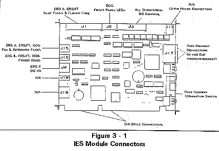
Refer to Figure 3-1 to identify the IES connector locations.
Instructions
1. Configure the data highway ID number and termination switch on the IES as explained in Chapter 2 - Configuration.
2. Perform an orderly shutdown of the Cubix subsystem.
3. Power down the subsystem and remove the power plug.
! If the module is being installed in a Cubix ERS/FT subsystem, it is only necessary to switch off power to the group in which the IES will be installed.
4. Remove the access cover to the bus slots.
5. If replacing a Cubix PA 3030 board with the IES module, remove the PA 3030 as follows:
' Disconnect any DBHD26 high density 26-pin cables from the end bracket of the PA 3030 and/or from the subsystem's rear I/O panel. There may be up to three of these cables.
' Disconnect two 26-pin cables from the PA 3030. Remove the 26-pin cable which is connected to the multiplexor.
' Disconnect the 14-pin and 34-pin ribbon cables and the 5-pin and 9-pin IDC connector cables from the PA 3030. Disconnect all cables attached to the NIC servicing the PA 3030. Remove the end bracket retainers for both boards, and remove the boards.
6. If the IES is being installed in a BOS, seat the module in the slot labeled Sensor. Otherwise, seat the IES module in slot 16. Secure the IES with the retaining screw provided.
7. Follow the internal cabling instructions for the type of subsystem in which the IES is being installed.
' Connect the 34-pin ribbon cable from the IES J1 connector to J5 labeled IES of the ERS II backplane (near the power supply). Make certain that the cable exits the connector toward the power supply with pin one forward (toward the mux).
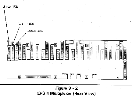
' Connect the 26-pin ribbon cable from the IES J2 connector to J20 of the multiplexor (second 26-pin connector away from the power supply as illustrated in Figure 3-2). Make certain that pin one of the cable is facing up.
' Connect the 2-pin cable from the IES J16 connector to J7 labeled IES on the ERS II backplane.
' Connect the 4-pin cable from the IES J15 connector to the 3-pin J11 connector on the ERS II multiplexor (refer to Figure 3-2).
' Connect the 4-pin Molex IES J4 connector to J10 on the ERS II multiplexor (refer to Figure 3-2). A special jumper consisting of a Molex connector with a wire "loop back" is installed in J10 on ERS II multiplexors that are not shipped with an IES. Remove this jumper before connecting J10 to J4 on the IES.
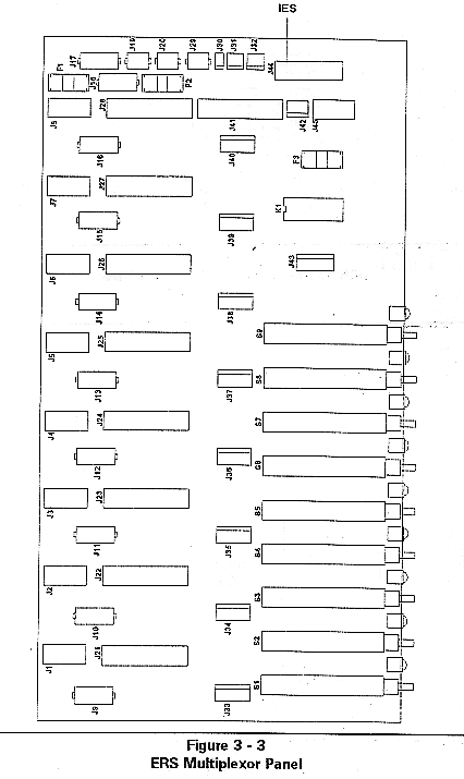
' Connect the 26-pin ribbon cable from the IES J3 connector to the multiplexor panel connector J44 (refer to Figure 3-3).
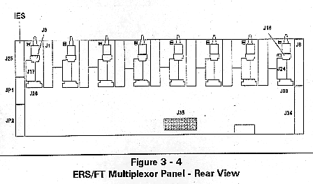
' Connect the 26-pin ribbon cable from the IES J3 connector to the multiplexor panel connector J25. J25 is accessible from the rear of the multiplexor panel (refer to Figure 3-4).
' On the ERS/FT backplane locate connector J3 labeled SUPERVISOR. This connector is located on the right front edge of the backplane when the ERS/FT is viewed from the top and front. Connect the 34-pin ribbon cable from IES J1 to the backplane connector J3.
' On the ERS/FT power supply backplane locate the J17 connector labeled PS GOOD. This is located on the right side of the ERS/FT subsystem when viewed from the top and front and partially underneath the multiplexor unit. Connect the 2-wire Molex connector from IES J16 to the power supply backplane connector J17.
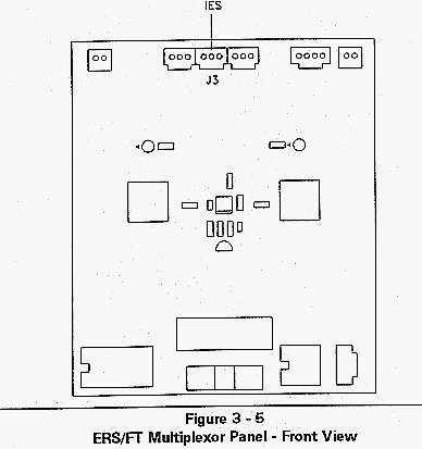
' Connect the 4-wire Molex connector from IES J15 to the multiplexor panel 3-wire connector J3. J3 is accessible from the front of the multiplexor panel (refer to Figure 3-5).
! This connection is not available on some early ERS/FT models. On the older models, J3 is a 4-pin Speaker connector.
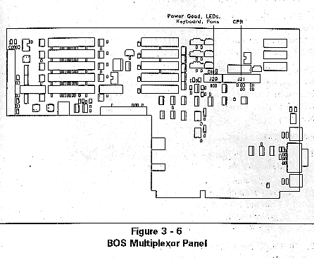
' Connect the 10-pin ribbon cable from the IES J2 connector to the multiplexor panel connector J20 (refer to Figure 3-6).
' Connect the 26-pin ribbon cable from the IES J3 connector to the multiplexor panel connector J21 (refer to Figure 3-6).
' Connect the Molex connectors J15 and J16 on the IES to the 2-connector end of the 3-connector "Y" cable. Connect the other end of the "Y" cable to the power supply connector J5 labeled IES. J5 is located immediately to the left of the main power connector on the power supply circuit board.
8. If the BC Supervisor is not already installed and connected to the data highway, follow the instructions in the BC Supervisor Installation section later in this chapter.
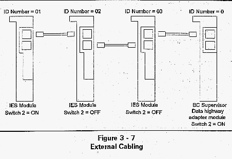
9. Each IES module and the adapter for the BC Supervisor have two RJ-11 jacks. Each jack is wired in parallel so that the external cabling does not require any T-adapter jacks. Connect each IES module in a daisy-chain fashion as shown in Figure 3-7. The total length of the chain should be no more than 150 feet.
Note: The data highway cable is a 6-conductor cable with RJ-11 connectors. The cable is wired with pin 1 connected to pin 1. Normal telephone cable has pin 1 connected to pin 6. Therefore telephone cable cannot be used in place of the Cubix supplied data highway cable.
Ensure that the two end connections have the termination switch ON and the middle connections have the termination switch in the OFF position.
10. Reassemble the subsystem. Power on all of the computers and refer to the IES Supervisory System Guide to Operations for further instructions on setup and use.
A BC xxx5 Cubix processor must run BCVision (this processor is the BC Supervisor). A BC xxx5 is any Cubix processor with "5" as the last digit of the product model name (BC 3035, BC 4035, etc.). Note that a BC 3030, BC 4030, or BC 4000 processor cannot be the BC Supervisor.
One BC Supervisor can supervise 31 IES modules in 31 different subsystems. The Cubix Data Highway Adapter connects the BC Supervisor to the data highway. This adapter can only be fitted to the COM2 port of the BC Supervisor. The BC Supervisor manages the data highway.
Instructions
1. Install the BC Supervisor in slot 15 (if a BOS will hold the BC Supervisor, place the BC in any available slot).
! If the integrated ethernet adapter on the BC Supervisor is not to be used and network communications are required, a NIC must be installed in the same slot group as the BC Supervisor. This may require moving the BC Supervisor to a different slot. Install the NIC at this time.
2. If the BC Supervisor will be at the end of the data highway chain, set switch "2" of the data highway adapter to the ON (down towards the board) position. Otherwise, set it to the OFF (up) position.
3. Select an open slot and using the supplied L-bracket secure the adapter with the retaining screw
OR
using the two elbow brackets supplied, secure to the auxiliary junction panel on the rear of the subsystem using the screws provided.
4. Attach the supplied 10-conductor ribbon cable from the adapter to the COM2 port of the BC Supervisor. Ensure the colored cable end connects to pin 1 of each box header. Pin 1 of the box header is indicated by a square pad on the solder side of the boards.
This document, and all Web contents, Copyright © 1997
by Cubix Corp., Carson City, NV, USA.