Backplane Configuration
Backplanes
The key to flexibility in Cubix Systems is the backplane. It is installed in the bottom of the system, and determines how many BC Series computers can be installed, and what bus or bus's are supported (ISA, EISA, or PCI).
The above photo shows a "8 x 2 ISA " backplane. The 8 signifies the number of groups, the 2 signifies the number of slots per group, and ISA specifies the Bus type.
With this backplane, you can install up to 8 BC series plug-in computers. Each group will contain the plug-in computer and one additional slot for third party boards, such as an internal modem, or fax board.
Each group with a BC series plug-in computer becomes an independent computer in the system.
Backplane Configurations
To increase the number of available configurations, some system backplanes can be reconfigured for a different number of groups, and slots per group. This is done by using shunt slots and shunt boards.
In the picture above, notice the black slots. They are ISA slots for the BC Series plug-in motherboards. Each group of ISA slots is separated by a brown connector called a shunt slot.
If the shunt slot is empty, there is no physical connection between the groups on either side of the shunt slot.
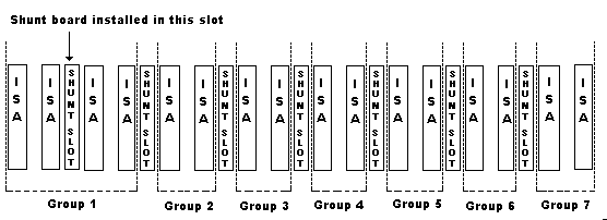
If a shunt board is installed in a shunt slot, the groups on either side of the shunt slot, are now physically combined into one group.
For example, if a shunt board is installed between group 1 and group 2 in a 8 x 2 ISA backplane:
Group 1 would now have 4 available slots instead of two.
The backplane would now have 7 groups (1 group of 4 slots and 6 groups of 2 slots).

Note: Not all backplanes can be reconfigured! If you do not have shunt slots BETWEEN the groups on the backplane, then it is a fixed configuration that cannot be changed.
Installing Shunt Boards
1. Turn off power the system. You do not need to remove the backplane from the system to install the shunt boards, although you may have to remove some of the boards to access the shunt slots.
2. Insert the shunt board into the shunt slot. The shunt board is keyed.
3. Push down evenly on the shunt board until it is fully inserted.
To remove a shunt board, lift up evenly on the both ends until the board is loose enough to remove. Lifting up on one end only may break the shunt board.
Systems | Circuit Boards | Other Products | Software | Hardware Identifier
Other Vendors | Technical Notes | Downloads | Search | Support Home Page
This document, and all
Web Site contents, Copyright ©
2000 by Cubix Corp., Carson City, NV, USA.