ERS II and
ERS/FT II
Chapter 3 - System Components
The Series II Subsystems may be described in terms of the following components:
Each component is described in the subsequent sections.
The power supply bay is located on the right side of the subsystem when viewing the front of the enclosure. This bay houses the single (ERS II) or dual (ERS/FT II) 375 watt power supplies. The purpose of the dual supplies in the ERS/FT II is to provide fault tolerance in the event of a single power supply failure. Fault tolerance is further supported by separate power input receptacles which allow each supply to be powered by a separate power source.
LEDs located on each power supply reflect the status of the supply. These LEDs are located on the top of each supply. A green LED indicates that the supply is functioning and providing power to the subsystem. An amber LED indicates a power supply fault. Because the LEDs on the power supplies are only visible when the top panel is removed from the unit, the ERS/FT II provides a duplicate set of LEDs on the front panel console.
The Cubix power supply is contained in a canister type of enclosure to make replacement as straightforward as possible. Each supply is fan cooled. The power supply load should be limited to 375 watts average, and the air inlet temperature of the subsystem should be maintained between 0 and 40 degrees Celsius. Appendix B - Power Supply contains load considerations and BTU calculations.
The disk drive bay is located in the front of the subsystem behind the front panel. The purpose of the disk drive bay is to provide a location for mounting disk drives used by the computers in the subsystem. One of three possible drive configurations may be specified at the time the subsystem is manufactured. The configuration only determines what types of disk drives the bay will accommodate. The drives themselves may be installed at the time the subsystem is manufactured or they may be added at a later date.
All of the disk drive bay configurations support a single third-height 3.5" floppy diskette drive with the floppy drive door accessible from the front of the subsystem. This is referred to as the "muxed floppy", and it is shared between all of the BC processors installed in the subsystem. All configurations also provide vertical mounting locations for hard drives. Hard drive mounts are designed to accommodate either a single third-height 3.5" disk drive or two of the 2.5" mini disk drives used with the Cubix QL Series processors.
The standard disk drive bay configuration provides nine vertical drive mounts. One is for the muxed floppy drive, leaving eight locations in which to mount hard disk drives. Each hard drive mounting location will accommodate one third-height 3.5" drive or two 2.5" drives, providing for a maximum of eight 3.5" or sixteen 2.5" drives in the bay. Note that the types of hard disk drives installed may be mixed, so that 3.5" drives may be installed in some locations and 2.5" drives in others. Typically, a single 3.5" drive is installed in each location, allowing each of the eight possible BC processors installed in the subsystem to have one dedicated hard disk drive. Refer to Figure 3-1.
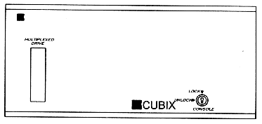
Figure 3-1
Drive Opening - Standard Configuration
Optional drive bay configurations may be substituted for the standard configuration. One option allows for installation of a half-height 3.5" tape drive. In this configuration, the tape drive occupies two of the vertical mounting locations provided in the standard configuration for hard disk drives, leaving only six. Therefore, six 3.5" or twelve 2.5" drives may be installed with the tape drive. Like the disk drives, the tape drive is mounted vertically in the subsystem. Access to the tape drive is via the front of the subsystem as illustrated in Figure 3-2.
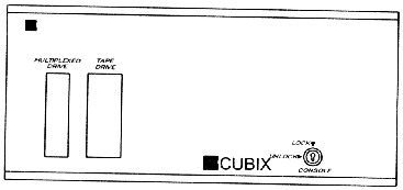
Figure 3-2
Drive Opening - Tape Option
The other disk drive bay configuration is designed to accommodate a CD ROM drive as well as a half-height 3.5" tape drive. The CD ROM drive is installed horizontally and has a 5.25" width. The tape drive is installed horizontally on top of the CD ROM drive as illustrated in Figure 3-3. These drives occupy four of the mounting locations provided in the standard configuration for hard disk drives, leaving only four. Therefore, four 3.5" or eight 2.5" drives may be installed with the tape and CD ROM drives.
Refer to Table 3 - 1 for a summary of disk drive bay configurations.
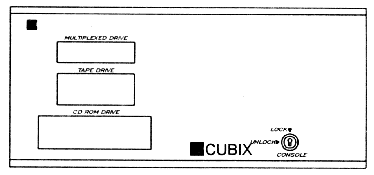
Figure 3-1
Drive Opening - Tape & CD Option
Table 3-1
Disk Drive Bay Configuration
| Description | Max 3.5" Drives |
Max 2.5" Drives |
Muxed Floppy |
Tape Drive |
CD ROM Drive |
| Standard | 8 |
16 |
Yes |
No |
No |
| Tape Drive Option | 6 |
12 |
Yes |
Yes |
No |
| CD ROM Option | 4 |
8 |
Yes |
Yes |
Yes |
* Half-height drives may also be accommodated. Consult a sales representative for information on half-height drive support.
* The Cubix SafeStor/FT enclosure provides additional disk drive storage. Consult a sales representative for information on the SafeStor/FT.
The processor bay is located in the rear of the subsystem. The processor bay contains the 16-slot backplane that may be divided into multiple groups of at least two slots each. One BC processor must be installed per group of slots, with the remaining slots in the group available as standard expansion slots. The slots run lengthwise in the bay (front to back) so that the end brackets of the boards installed in the backplane are accessible from the rear of the subsystem.
Each slot on the backplane of the subsystem is equipped with a +5vdc eight amp fuse. These fuses are constantly monitored by the IES. If the IES detects that a fuse has lost power, an alarm is generated to the BC Supervisor and annunciated on the console (ERS/FT II only).
On the ERS II, an alarm is generated any time a slot loses power while power to the subsystem is turned on. On the ERS/FT II, since groups may be turned off independently of one another, an alarm will be generated only if a slot loses power while power to its group is turned on.
The ERS II supports an ISA backplane. The ERS/FT II supports ISA, EISA, and combination ISA/EISA configurations.
ISA Configurations
The Cubix ISA backplane technology is based upon the concept of "joining", or "shunting", groups of slots together. When the backplane is manufactured, it consists of multiple groups of slots that are not electrically joined together. Between the standard ISA slots are special shunt slots (these slots resemble EISA slots in appearance). By inserting a Cubix shunt board into the shunt slot, the adjacent two groups are joined, forming a larger backplane segment.
For example, assume that the backplane is divided into eight groups of two slots each. These groups are identified as Group 1, Group 2, etc., and ending with Group 8. By inserting a shunt board between groups 1 and 2, the backplane is reconfigured to contain only seven groups. Group 1 contains 4 slots (previously assigned to groups 1 and 2), and groups 2 through 7 contain 2 slots each.
CAUTION!
A maximum of 10 slots may be joined together using shunt boards. Failure to comply with this limitation may result in loss of data.
Two ISA backplanes are manufactured: one consists of eight groups of two slots each; the other consists of one group of fourteen slots and one group of two slots. The various configurations that are available by inserting shunt boards into these backplanes are illustrated in Table 3 - 2.
EISA and EISA/ISA Configurations
Backplanes that contain EISA slots are available only for the ERS/FT II subsystem. EISA slots cannot be configured using the shunt technology described for ISA backplanes. Therefore, Cubix manufactures several EISA backplanes to satisfy the various requirements for backplane group configurations. On the backplanes that include both EISA and ISA slots, the ISA slots may be joined using the shunt technology, but the EISA slots cannot. Therefore, no shunt slots are provided between the EISA groups.
The EISA and EISA/ISA backplanes, including the various shunting configurations, are listed in Table 3 - 3.
Table 3 - 2
ISA Backplane Confiaurations
# of Groups |
Group 1 |
Group 2 |
Group 3 |
Group 4 |
Group 5 |
Group 6 |
Group 7 |
Group 8 |
*1 |
16 ISA |
- |
- |
- |
- |
- |
- |
- |
*2 |
14 ISA |
2 ISA |
- |
- |
- |
- |
- |
- |
2 |
10 ISA |
6 ISA |
- |
- |
- |
- |
- |
- |
2 |
8 ISA |
8 ISA |
- |
- |
- |
- |
- |
- |
3 |
10 ISA |
4 ISA |
2 ISA |
- |
- |
- |
- |
- |
3 |
8 ISA |
6 ISA |
2 ISA |
- |
- |
- |
- |
- |
3 |
8 ISA |
4 ISA |
4 ISA |
- |
- |
- |
- |
- |
3 |
6 ISA |
6 ISA |
4 ISA |
- |
- |
- |
- |
- |
4 |
8 ISA |
4 ISA |
2 ISA |
2 ISA |
- |
- |
- |
- |
4 |
6 ISA |
6 ISA |
2 ISA |
2 ISA |
- |
- |
- |
- |
4 |
4 ISA |
4 ISA |
4 ISA |
4 ISA |
- |
- |
- |
- |
5 |
4 ISA |
4 ISA |
4 ISA |
2 ISA |
2 ISA |
- |
- |
- |
5 |
6 ISA |
4 ISA |
2 ISA |
2 ISA |
2 ISA |
- |
- |
- |
6 |
6 ISA |
2 ISA |
2 ISA |
2 ISA |
2 ISA |
2 ISA |
- |
- |
6 |
4 ISA |
4 ISA |
2 ISA |
2 ISA |
2 ISA |
2 ISA |
- |
- |
7 |
4 ISA |
2 ISA |
2 ISA |
2 ISA |
2 ISA |
2 ISA |
2 ISA |
- |
8 |
2 ISA |
2 ISA |
2 ISA |
2 ISA |
2 ISA |
2 ISA |
2 ISA |
2 ISA |
* Requires the backplane manufactured with one group of 14 slots and one
group of 2 slots. All other configurations require the backplane with
eight groups of two slots each.
Table 3 - 3
EISA and EISA/ISA Backplane Confiaurations
# of Groups |
Group 1 |
Group 2 |
Group 3 |
Group 4 |
Group 5 |
Group 6 |
Group 7 |
Group 8 |
1 |
8 EISA 8 ISA |
- |
- |
- |
- |
- |
- |
- |
2 |
8 EISA |
8 EISA* |
- |
- |
- |
- |
- |
- |
2 |
8 EISA |
8 ISA |
- |
- |
- |
- |
- |
- |
2 |
8 EISA 4 ISA |
4 ISA |
- |
- |
- |
- |
- |
- |
2 |
8 EISA 6 ISA |
2 ISA |
- |
- |
- |
- |
- |
- |
3 |
8 EISA 4 ISA |
2 ISA |
2 ISA |
- |
- |
- |
- |
- |
3 |
8 EISA |
6 ISA |
2 ISA |
- |
- |
- |
- |
- |
3 |
8 EISA |
4 ISA |
4 ISA |
- |
- |
- |
- |
- |
3 |
4 EISA |
4 EISA |
8 ISA |
- |
- |
- |
- |
- |
4 |
4 EISA |
4 EISA |
4 EISA |
4 EISA* |
- |
- |
- |
- |
4 |
8 EISA |
4 ISA |
2 ISA |
2 ISA |
- |
- |
- |
- |
4 |
8 EISA 2 ISA |
2 ISA |
2 ISA |
2 ISA |
- |
- |
- |
- |
4 |
4 EISA |
4 EISA |
6 ISA |
2 ISA |
- |
- |
- |
- |
4 |
4 EISA |
4 EISA |
4 ISA |
4 ISA |
- |
- |
- |
- |
5 |
8 EISA |
2 ISA |
2 ISA |
2 ISA |
2 ISA |
- |
- |
- |
5 |
4 EISA |
4 EISA |
4 ISA |
2 ISA |
2 ISA |
- |
- |
- |
6 |
4 EISA |
4 EISA |
2 ISA |
2 ISA |
2 ISA |
2 ISA |
- |
- |
8 |
2 EISA* |
2 EISA* |
2 EISA* |
2 EISA* |
2 EISA* |
2 EISA* |
2 EISA* |
2 EISA* |
| * Indicates an EISA group that will accommodate either an EISA or ISA BC processor. | ||||||||
A multiplexor (mux) integrated into the Series II Subsystems allows a single monitor, keyboard, mouse, and floppy drive to be shared by multiple processors. In addition, many of the front panel functions, such as the reset processor pushbutton, will only affect the selected BC processor. (The selected BC's slot number displays on the front panel.)
The multiplexor is a printed circuit board located between the disk drive bay and the processor bay. The mux board is installed vertically and crosswise in the subsystem.
The mux operates on the concept of channels (refer to Figure 3-4 ). There is a separate mux channel for each possible BC processor in the subsystem, yielding a total of eight mux channels. The mux connects the BC processors to the monitor, keyboard, mouse, and floppy disk drive (these peripherals are referred to as the "muxed devices"). An operator may select a BC processor via the front panel of the subsystem. When a BC is selected, the mux enables the channel corresponding to that BC, allowing the signals for the monitor, keyboard, mouse, and floppy drive to pass through the channel to the selected BC processor. When a different BC is selected by the operator, the mux enables the channel of the new BC processor which takes control of the muxed devices.
In addition to muxing the monitor, keyboard, mouse, and floppy devices between processors in a single subsystem, the multiplexor shares all of these devices except the floppy drive between multiple subsystems installed in a single Cubix System 1010 cabinet. This allows a single monitor, keyboard, and mouse to service all of the processors in a cabinet. One floppy drive is required per subsystem to service all of the processors in that enclosure.
ERS/FT II Custom Channel
In addition to the eight standard channels on the multiplexor, the ERS/FT II has a ninth channel referred to as the "custom channel" (refer to Figure 3-5 ). This channel is not available on the ERS II. The custom channel may be attached to Cubix QL Series processors, connecting them to the muxed devices for installation purposes. The custom channel may be enabled or disabled via an option switch (refer to the Custom Channel Configuration section in Chapter 4).
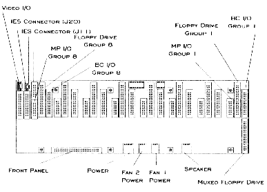
Figure 3-4
ERS II Multiplexor (Rear View)
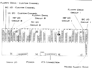
Figure 3-5
ERS/FT II Multiplexor (Rear View)
The IES (Intelligent Environmental Sensor) provides management functions for the Series II Subsystems. The IES is integrated into ERS/FT II subsystems as a printed circuit board installed directly in front of the mux board. In the ERS II, a separate IES module may be installed in one of the slots on the backplane in the processor bay.
The IES continuously monitors the environmental conditions of the subsystem, including the temperature, voltages, fan rotation, and fuses. The IES also monitors the activity of each BC processor in the subsystem. If a fault occurs, the IES reports the fault to the BC Supervisor. In the event of a BC processor failure, as might occur as the result of a software application error, the IES may be configured to automatically reset the BC.
IES Functions
The IES performs the following functions when installed with an IES Supervisory System:
For a complete description of these functions, refer to the IES Supervisory System Guide to Operations or the Cubix Management System Installation Guide.
The IES is part of the IES Supervisory System, which consists of a BC processor dedicated to running the BCVision management application. This BC processor is referred to as the BC Supervisor, and it can supervise up to thirty-one subsystems and their processors. Each subsystem must include an IES. A Cubix out of band data highway connects the BC Supervisor to the IES in each subsystem.
Additional management of the Cubix subsystems and processors is provided in the optional Cubix Management System (CMS) software application. CMS is an SNMP based management package that manages all Cubix devices on a network. The BC Supervisor provides the interface between the IES Supervisory System and CMS. Refer to Figure 3-6 for a block diagram of the IES Supervisory System architecture.
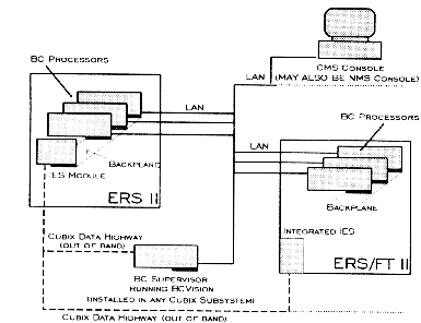
Figure 3-6
IES Supervisory System Block Diagram
The front panel of the Series II Subsystems serves as the operator console. From this console, the functions described below are available. Specific front panel operational instructions are in the section Console Operation.
Console Functions
* In subsystems equipped with a tape drive or CD ROM drive, access to these devices is also via the front panel.
ERS/FT II Functions
The ERS/FT II front panel provides all of the above functions in addition to the following functions not supported by the ERS II:
Console Operation
Refer to Figure 3-7 and Figure 3-8 for illustrations of the ERS II and ERS/FT II front panel consoles. These consoles operate as described below.
* Hint: The up and down pushbuttons will repeat their function if pressed for more than half a second on the ERS/FT II (this feature is not available on the ERS II).
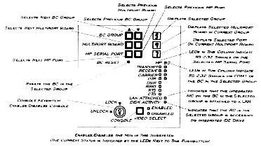
Figure 3-7
ERS II Console
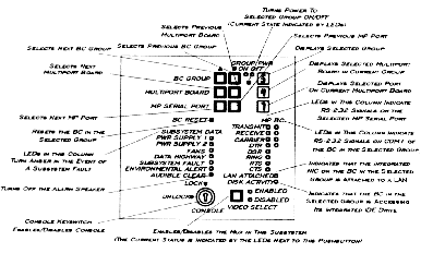
Figure 3-8
ERS/FT II Console
BC Group
The operator may select a BC group using the up and down pushbuttons on the front panel. The currently selected group number is displayed. "Group" refers to a group of slots on the backplane that are connected together and contain a BC processor, thus comprising one computer in the subsystem. Groups are numbered one to eight.
When a group is selected, its channel on the multiplexor is enabled, thus connecting the selected group to the monitor, keyboard, mouse, and floppy drive. Several of the other front panel operations described below apply only to the selected BC group.
The BC group up and down pushbuttons are disabled if the console is locked. In addition, the subsystem must be enabled for the muxed devices to be controlled by the BC group selection (refer to the Video Select section).
On the ERS/FT II subsystem only, the ninth custom multiplexor channel is controlled by the BC group pushbuttons. Assuming that the custom channel is enabled, if the last group is selected and the up pushbutton is pressed, the ninth channel will be selected. The letter "C" is displayed for the group number. Likewise, the custom channel may be selected by pressing the down pushbutton when group one is selected.
BC Reset
The BC processor in the selected BC group may be reset via a pushbutton on the front panel. This pushbutton is recessed to prevent accidental resets. Use a pointed object (such as a pen) to push the button and reset the processor.
The BC Reset function is operational only if the subsystem is enabled and the console is unlocked. Refer to the Video Select and Console Keylock sections for more information.
* The operation of the BC Reset pushbutton may be modified using the option switch as described in the Keylock Option Configuration section of Chapter 4.
BC Port Activity
A column of LEDs labeled "BC" indicate the activity of the COM1 RS 232 signals on the selected BC. The LED is illuminated if the signal is true. The signals displayed are transmit, receive, carrier, and data terminal ready (DTR).
LAN Attached
The current BC Series of products include an integrated Ethernet controller (previous versions of the BC boards did not include this component). Current boards are identified by a "5" in the last digit of their product name (BC 3035, BC 4035, BC 5055, etc.) If the selected BC has an integrated Ethernet controller and the controller is connected to a LAN, the LED labeled "LAN Attached" will be illuminated.
Disk Activity
All BC processors are equipped with an integrated IDE hard disk drive controller. Any time IDE disk access occurs on the selected BC, the LED labeled "Disk Activity" will be illuminated.
Multiport Board
Cubix manufactures an intelligent eight port serial board (the MP 2008 product). These multiport boards are often installed in subsystems to provide ports for remote communications. The MP 2008 is a slave board that must be installed in a group with a BC processor.
Each MP 2008 is assigned an address with a switch on the MP board. This address must be unique within the group in which the board is installed. Addresses should be configured consecutively. When installing MP boards, configure the first MP in the group at address 0, the second in the same group at address 1, etc. Repeat this process for each group in which MP boards are to be installed, beginning with address 0 in each group.
If the selected BC group contains a multiport board, the first MP 2008 board (i.e. at address 0) will automatically be selected. A "0" will be displayed as the multiport board number. The operator may select another MP board using the up and down pushbuttons on the front panel. The multiport board number will be displayed appropriately.
MP Serial Port
When a multiport board is selected, the RS 232 signals of the first port on the board are displayed on the front panel (refer to MP Port Activity below). The number of this port is displayed as the MP Serial Port. Ports are numbered zero to seven, and may be selected via the MP serial port up and down pushbuttons.
MP Port Activity
A column of LEDs labeled "MP" indicate the activity of the RS 232 signals on the selected MP port. The LED is illuminated if the signal is true. The signals displayed are transmit, receive, carrier, data terminal ready (DTR), data set ready (DSR), ring, request to send (RTS), and clear to send (CTS).
Video Select
With the exception of the floppy drive, the muxed devices may be shared by all of the subsystems installed in a single Cubix cabinet (i.e. the monitor, keyboard, and mouse). The Video Select pushbutton determines which subsystem is enabled to control these devices. Only one subsystem may be selected at a time. The LED labeled "Enabled" is illuminated when a subsystem is selected. The LED labeled "Disabled" is illuminated when this subsystem is not selected. The pushbutton labeled "Video Select" is a toggle that enables\disables the subsystem.
When a subsystem is enabled, the muxed devices are under its control. In addition, the BC Reset function is operational, allowing a BC to be reset via a button on the console. When a subsystem is disabled, the muxed devices are not available to the subsystem and the BC Reset function is not operational. Note that a disabled subsystem can access none of the muxed devices, including the floppy drive (to override this feature refer to the Keylock Option Configuration section of Chapter 4).
To enable a subsystem, press the Video Select pushbutton. To disable a subsystem, press the Video Select pushbutton again. Note that a subsystem is also disabled when another subsystem with which this subsystem is sharing the muxed devices is enabled.
Console Keylock
A keylock resides on the front panel. When the key is in the locked position, the following functions, as shown in Figure 3-9, are disabled:
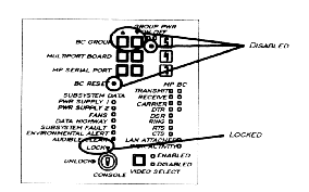
Figure 3-9
Console Lock
These functions are disabled when the console is locked regardless of the conditions under which the lock occurs.
On the ERS/FT II, if the Video Select pushbutton is used to disable the subsystem and then the console is locked, all console functions are disabled. The panel displays "LOC" in the three positions normally used to display the BC Group, Multiport Board, and MP Serial Port numbers as illustrated in Figure 3-10. In this state, none of the pushbuttons are operational.
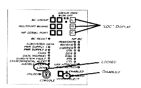
Figure 3-10
ERS/FT II Console Disabled
However, if the subsystem is enabled when the console is locked, the front panel displays the selected BC Group, Multiport Board, and MP Serial Port as normal. (Note that this is also the case if the subsystem is disabled because another subsystem is enabled and then the console is locked).
! The behavior of the muxed devices when the console is locked may be modified using the option switch. Refer to the Keylock Option Configuration section in Chapter 4 for an explanation of the option switch.
ERS/FT II Functions
The ERS/FT II subsystem supports the following console functions in addition to those supported by the ERS II.
Group Power
The selected BC Group represents a group of slots on the backplane. The power to these slots may be turned on or off via the Group Power pushbutton. This pushbutton is recessed to prevent a group from being unintentionally powered on or off. Use a pointed device (such as a pen) to press the group power pushbutton. The pushbutton functions as a toggle, turning power on if it is already off or turning power off if it is already on. The current state of power on the selected group is illustrated by the Group Power LEDs. If power is applied to the group, the green Group Pwr On LED is illuminated. If power is not applied to the group, the amber Group Pwr Off LED is illuminated. Understand that pressing the Group Pwr pushbutton applies power to or removes power from the selected group only. Other groups in the subsystem are not affected.
* The custom channel is an I/O channel only. Therefore, when selected, the group power switch is disabled and will display an ON condition.
Subsystem Data
A column of LEDs provide the following diagnostic information describing the subsystem:
Audible Clear
If an environmental alarm occurs in the ERS/FT II, the alarm will cause the speaker to sound in addition to illuminating the appropriate LED on the front panel and generating an alarm to the BC Supervisor. The speaker will continue to sound until the alarm clears or the Audible Clear pushbutton is pressed.
Power On Self Tests
When the ERS/FT II is turned on, it performs diagnostic tests. If a fault is detected, an error code is displayed on the console. Refer to the Power On Self Tests section in Chapter 5 for more information.
I/O connectors are located on the rear of the subsystem. The rear of the subsystem is divided into three panels: the I/O panel, the processor bay panel, and the rear panel (refer to Figure 3-11 and Figure 3-12).
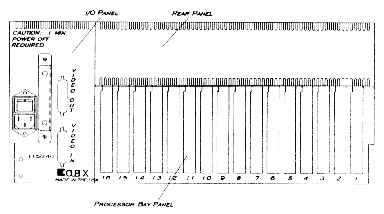
Figure 3-11
ERS II Rear Panels
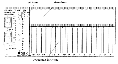
Figure 3-12
ERS/FT II Rear Panels
I/O Panel
The I/O Panel is located on the left when viewing the rear of the subsystem. The connectors on the I/O panel are explained below. Instructions for using these connectors to install the subsystem are in Chapter 2 - Subsystem Installation.
Processor Bay Panel
The processor bay panel occupies the right lower section the rear of the subsystem. It contains space for sixteen standard PC style board end brackets numbered one to sixteen. As boards are installed in the processor bay, their end brackets will occupy a position on the processor bay panel, allowing access to any connectors on these end brackets from the rear of the subsystem.
Rear Panel
An optional rear panel may be installed in the space above the processor bay panel. The purpose of the rear panel is to provide a space to mount connectors that are not provided on the end brackets of the boards installed in the subsystem.
Because a Cubix processor board is a complete computer on a single board, there are more I/O functions available than can be accommodated on the end bracket of the board. Therefore, only the connectors that are most often required are mounted on the end bracket. Additional connectors may be installed in the rear panel. This method is applied to both the BC and QL Series of products.
A rear panel is a piece of metal with holes designed to accommodate specific connectors cut into the panel. The holes may be filled with connectors for the boards installed in the subsystem. There are several rear panel configurations available. Consult a sales representative to select the panel that best suits the connector requirements.
This document, and all Web contents, Copyright © 1997 by Cubix Corp., Carson City, NV, USA.