 |
|
|
|
ERS II and
ERS/FT II
Chapter 2 - Subsystem Installation
This chapter provides instructions for installing a Series II Subsystem. The subsystem should already be properly configured as described in Chapter 4 - Configuration. Instructions for installing subsystem components, such as processor boards and disk drives, may be found in Chapter 6.
The sections in this chapter describe subsystem installation as follows:
WARNING!
CUBIX SERIES II SUBSYSTEMS MUST BE SERVICED AND CONFIGURED BY QUALIFIED SERVICE PERSONNEL ONLY.
THIS EQUIPMENT IS DESIGNED AND DESIGNATED AS CLASS 1 ELECTRONIC EQUIPMENT TO MEET ALL REQUIRED SAFETY STANDARDS. TWO PROPERLY GROUNDED POWER CORDS IN GOOD PHYSICAL CONDITION MUST BE USED TO POWER THE SUBSYSTEM FROM PROPERLY GROUNDED WALL RECEPTACLES. THE USE OF FRAYED, CRACKED, OR ABRADED POWER CORDS, OR POWER CORDS WITH A DAMAGED THIRD WIRE SAFETY GROUND CONNECTION, OR POWER CORDS WITHOUT A THIRD WIRE SAFETY GROUND, ARE NOT THE RESPONSIBILITY OF CUBIX CORPORATION AND WILL VOID THE WARRANTY. USE ONLY 3/18 AWG SVT OR SJT CORDS WITH AN APPROVED IEC 320/C13 CONNECTOR TO OPERATE THE SYSTEM.
The Series II Subsystems rack mount enclosures are designed for installation into Cubix System 1010 cabinets. The subsystems are standard 19" RETMA units and may be mounted into any cabinet that accommodates 19" RETMA devices (dimension requirements are illustrated in Figure 2-1 ). Follow the instructions below to install a subsystem into a Cubix System 1010 cabinet.
Refer to Figure 2-2 for an illustration of the subsystem mounting procedure.
1. Install any boards, storage devices, panels, connectors, or other devices into the subsystem as required (installation instructions are included in Chapter 6 - Component Installation).
2. Remove the middle and rear sliding rails from the sides of the subsystem.
3. With the middle rails still inserted into the rear rails, mount them into the cabinet using the four brackets provided.
4. Slide the subsystem on the front rails into the mounted middle rails.
CAUTION!
Do not leave the subsystem unattended while it is at full extension as the weight of the subsystem may cause the cabinet to tip over.
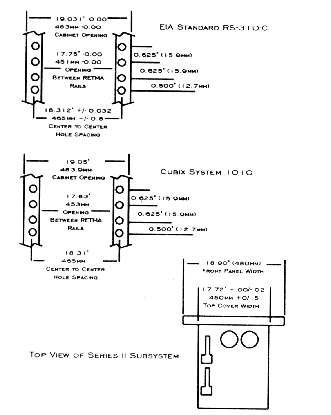
Figure 2-1
Mounting Dimensions
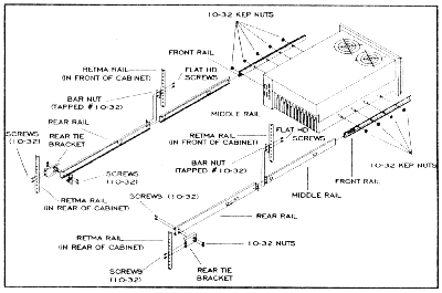
Figure 2-2
Subsystem II Cabinet Installation
5. Connect the monitor, keyboard, and mouse. These devices may be shared between multiple subsystems residing in a single cabinet. This is accomplished by daisy-chaining the subsystems together and connecting the last subsystem in the daisy-chain to a Video/Keyboard/Mouse Breakout Module (refer to Figure 2-3):
! If the muxed devices are to be shared with an old style ERS subsystem, refer to the ERS Integration section following these instructions.
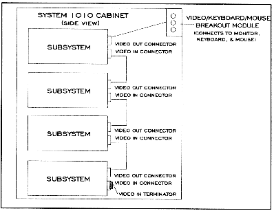
Figure 2-3
Video/Keyboard/Mouse Cabinet Installtion
6. If the monitor, keyboard, and mouse are not already connected to the breakout module, route the cables for these devices into the cabinet via a 1.75" access hole in the top cover and connect the cables to the breakout module.
7. If an IES Supervisory System is installed, configure the IES address and connect the data highway as described in the IES Installation instructions later in this chapter.
8. If a BC Supervisor resides in the subsystem, connect it to the data highway. The BC Supervisor is the BC processor dedicated to running BCVision, the user interface into the IES Supervisory System. A Cubix adapter board converts COM2 on the BC Supervisor to the appropriate RJ-11 data highway connectors on the rear panel of the subsystem.
Switch 1 next to the IES connectors is not used.
Note that if the BC Supervisor is to be connected to an IES in the same subsystem, the data highway cable must be routed from one of the IES RJ-11 connectors to one of the BC Supervisor RJ-11 connectors on the same rear panel.
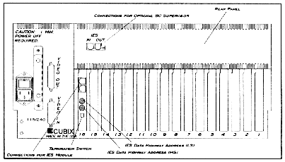
Figure 2-4
ERS II Data Highway Connectors
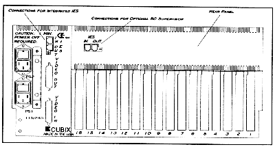
Figure 2-5
ERS/FT II Data Highway Connectors
9. Connect peripheral devices (such as modems, printers, etc.) as required.
10. Apply power to the subsystem. Use the Console Overview section later in this chapter to verify that the subsystem functions properly.
ERS Integration
The old-style ERS subsystems cannot be placed into a daisy-chain for the video/keyboard/mouse multiplexing. Only the ERS II, ERS/FT, and ERS/FT II products support this configuration. If older ERS subsystems are included in the cabinet, a cabinet multiplexor must be installed to support sharing a monitor, keyboard, and mouse with the ERS. In this case, connect the daisy-chain to the newer subsystems and to the breakout module as previously explained. Instead of connecting the breakout module to the muxed devices, connect it to an input on the cabinet multiplexor. Also connect each old-style ERS subsystem to an input on the cabinet multiplexor. Connect the monitor, keyboard, and mouse devices to the output channel on the cabinet multiplexor.
The Series II Subsystems of enclosures include a table top unit for installations where only one subsystem is required and a cabinet is not needed.
1. Install any boards, storage devices, panels, connectors, or other devices into the subsystem as required (installation instructions are included in Chapter 6 - Component Installation).
2. Place the subsystem in a suitable storage location.
3. Connect the monitor, keyboard, and mouse:
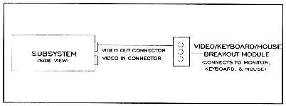
Figure 2-6
Video/Keyboard/Mouse Table Top Installation
4. If an IES Supervisory System is installed, configure the IES address and connect the data highway as described in the IES Installation instructions later in this chapter.
5. If a BC Supervisor resides in the subsystem, connect it to the data highway. The BC Supervisor is the BC processor dedicated to running BCVision, the user interface into the IES Supervisory System. A Cubix adapter board converts COM2 on the BC Supervisor to the appropriate RJ-11 data highway connectors on the rear panel of the subsystem.
Switch 1 next to the IES connectors is not used.
Note that if the BC Supervisor is to be connected to an IES in the same subsystem, the data highway cable must be routed from one of the IES RJ-11 connectors to one of the BC Supervisor RJ-11 connectors on the same rear panel.
6. Connect peripheral devices (such as modems, printers, etc.) as required.
7. Apply power to the subsystem. Use the Console Overview section later in this chapter to verify that the subsystem functions properly.
If an ERS II subsystem with no IES module is being installed, no IES installation is required.
The Cubix Data Highway is the out-of-band highway connecting devices on an IES Supervisory System (refer to the IES Supervisory System Guide to Operations for more information). Like the video/keyboard/mouse cable, the data highway is daisy-chained between subsystems.
Each IES connected to the same Cubix data highway must be assigned a unique data highway address. The BC Supervisor uses this address to identify and communicate with each IES. A unique address is required regardless of whether the IES is integrated into the subsystem (as in the ERS/FT II) or the IES is a stand alone module installed into a slot in the backplane of the subsystem (as in the ERS II).
Valid IES addresses range from 1 to 31 (address 0 is reserved for the BC Supervisor). The default address of the IES is configured to 1 by Cubix manufacturing.
IES Module (ERS II)
In ERS II subsystems, the IES is a stand alone module that may optionally be installed in a slot of the backplane. The IES address is configured with two rotary switches on the module. Access to these switches can be gained from the end bracket of the module from the rear of the ERS II as illustrated in Figure 2-4. This chapter assumes that the IES module is already installed in the subsystem. Module installation instructions may be found in Chapter 6 - Component Installation.
The switch labeled MS selects the Most Significant (or high order) hexadecimal digit of the IES address. The LS switch selects the Least Significant (or low order) hexadecimal digit of the IES address. Refer to Table 2 - 1 for switch settings.
After setting the IES address, connect the IES to the Cubix data highway:
Switch 1 of this DIP switch must always be in the ON (or down) position.
| IES Address | Hex Switch | IES Address | Hex Switch |
| (Decimal) | MS | LS | (Decimal) | MS | LS |
| 1 | 0 | 1 | 17 | 1 | 1 |
| 2 | 0 | 2 | 18 | 1 | 2 |
| 3 | 0 | 3 | 19 | 1 | 3 |
| 4 | 0 | 4 | 20 | 1 | 4 |
| 5 | 0 | 5 | 21 | 1 | 5 |
| 6 | 0 | 6 | 22 | 1 | 6 |
| 7 | 0 | 7 | 23 | 1 | 7 |
| 8 | 0 | 8 | 23 | 1 | 8 |
| 9 | 0 | 9 | 25 | 1 | 9 |
| 10 | 0 | A | 26 | 1 | A |
| 11 | 0 | B | 27 | 1 | B |
| 12 | 0 | C | 28 | 1 | C |
| 13 | 0 | D | 29 | 1 | D |
| 14 | 0 | E | 30 | 1 | E |
| 15 | 0 | F | 31 | 1 | F |
| 16 | 1 | 0 |
Integrated IES (ERS/FT II)
The ERS/FT II contains an integrated IES. The address of this IES is determined by an eight position DIP switch located on the top edge of the IES board, which is installed between the disk drive bay and the multiplexor board. Access to this switch can be gained as follows:
The IES address switch is the rightmost switch (closest to the power supply). Switches are numbered one to eight from left to right when viewed from the front of the subsystem. A switch is ON when it is in the up position, and OFF when it is in the down position. Table 2 - 2 contains valid IES switch configurations.
After setting the IES address, connect the ERS/FT II to the Cubix data highway. This is accomplished using the two RJ-11 connectors on the rear I/O panel of the subsystem as shown in Figure 2-5.
* Switch 2 under the IES connectors is not used.
Table 2-2
IES Address Configuration
IES Address |
DIP Switch Position 1 2 3 4 5 6 7 8 |
|||||||
1 |
OFF |
ON |
ON |
ON |
ON |
ON |
ON |
ON |
2 |
ON |
OFF |
ON |
ON |
ON |
ON |
ON |
ON |
3 |
OFF |
OFF |
ON |
ON |
ON |
ON |
ON |
ON |
4 |
ON |
ON |
OFF |
ON |
ON |
ON |
ON |
ON |
5 |
OFF |
ON |
OFF |
ON |
ON |
ON |
ON |
ON |
6 |
ON |
OFF |
OFF |
ON |
ON |
ON |
ON |
ON |
7 |
OFF |
OFF |
OFF |
ON |
ON |
ON |
ON |
ON |
8 |
ON |
ON |
ON |
OFF |
ON |
ON |
ON |
ON |
9 |
OFF |
ON |
ON |
OFF |
ON |
ON |
ON |
ON |
10 |
ON |
OFF |
ON |
OFF |
ON |
ON |
ON |
ON |
11 |
OFF |
OFF |
ON |
OFF |
ON |
ON |
ON |
ON |
12 |
ON |
ON |
OFF |
OFF |
ON |
ON |
ON |
ON |
13 |
OFF |
ON |
OFF |
OFF |
ON |
ON |
ON |
ON |
14 |
ON |
OFF |
OFF |
OFF |
ON |
ON |
ON |
ON |
15 |
OFF |
OFF |
OFF |
OFF |
ON |
ON |
ON |
ON |
16 |
ON |
ON |
ON |
ON |
OFF |
ON |
ON |
ON |
17 |
OFF |
ON |
ON |
ON |
OFF |
ON |
ON |
ON |
18 |
ON |
OFF |
ON |
ON |
OFF |
ON |
ON |
ON |
19 |
OFF |
OFF |
ON |
ON |
OFF |
ON |
ON |
ON |
20 |
ON |
ON |
OFF |
ON |
OFF |
ON |
ON |
ON |
21 |
OFF |
ON |
OFF |
ON |
OFF |
ON |
ON |
ON |
22 |
ON |
OFF |
OFF |
ON |
OFF |
ON |
ON |
ON |
23 |
OFF |
OFF |
OFF |
ON |
OFF |
ON |
ON |
ON |
24 |
ON |
ON |
ON |
OFF |
OFF |
ON |
ON |
ON |
25 |
OFF |
ON |
ON |
OFF |
OFF |
ON |
ON |
ON |
26 |
ON |
OFF |
ON |
OFF |
OFF |
ON |
ON |
ON |
27 |
OFF |
OFF |
ON |
OFF |
OFF |
ON |
ON |
ON |
28 |
ON |
ON |
OFF |
OFF |
OFF |
ON |
ON |
ON |
29 |
OFF |
ON |
OFF |
OFF |
OFF |
ON |
ON |
ON |
30 |
ON |
OFF |
OFF |
OFF |
OFF |
ON |
ON |
ON |
31 |
OFF |
OFF |
OFF |
OFF |
OFF |
ON |
ON |
ON |
A console is located on the front panel of each subsystem. Figures 2 - 7 and 2 - 8 provide overviews of the operation of the consoles on the ERS II and the ERS/FT II. For a detailed description of console functions, refer to Chapter 3 - Subsystem Components.
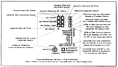
Figure 2-7
ERS II Console
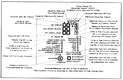
Figure 2-8
ERS/FT II Console
The following switches exist on the Series II Subsystems. An overview of each switch is provided in this section. For a detailed description of the functions controlled by these switches, refer to Chapter 4 - Configuration.
ERS II Switches
Both switches are located on the top of the multiplexor. A switch is OFF when it is pointing up and ON when it is pointing to the front of the subsystem.
ERS/FT II Switches
Both switches are located on the top of the IES board (the IES Address Switch is the one closest to the power supplies). A switch is OFF when it is pointing down and ON when it is pointing up. See Tables 2 - 3 and 2 - 4 for dip switch positions.
Table 2-3
Option Switch
| Description | DIP Switch Position |
| Monitor Only | 1 |
Monitor/Keyboard/Mouse/Reset |
2 |
| Floppy Channel 1 | 3 |
| Master Console Keylock | 4 |
| Custom Channel (ERS/FT II Only) | 5 |
| Off = Option Enabled On = Option Disabled | |
Table 2-4
ERS II Mux Channel Configuration Switch
| Description | DIP Switch Position |
| Multiplexor Channel 1 | 1 |
| Multiplexor Channel 2 | 2 |
| Multiplexor Channel 3 | 3 |
| Multiplexor Channel 4 | 4 |
| Multiplexor Channel 5 | 5 |
| Multiplexor Channel 6 | 6 |
| Multiplexor Channel 7 | 7 |
| Multiplexor Channel 8 | 8 |
| Off = Channel Enabled On = Channel Disabled | |
This document, and all Web contents, Copyright © 1997 by Cubix Corp., Carson City, NV, USA.