ERS II and
ERS/FT II
Addendum to User's Guide
This addendum to the Series II Subsystems User’s Guide documents the following:
Associated Documents
This addendum must be used in combination with the information provided in the following documents:
PCI MIBs and Possible Configurations
Cubix supplies three separate Master Interconnect Boards (MIBs) to satisfy the various PCI bus configuration requirements. Each PCI MIB and related configuration detail is discussed in the following sections.
Note: The ERS/FT II subsystem is the ONLY subsystem to support PCI MIBs.
2x5 PCI + 2x2 ISA MIB
Used only with the active PCI-to-PCI bus extender card, this MIB provides two groups of five slots each, and two groups of two slots each (see Important Note). In each five-slot group a BC 5090/5120/5150SE or SP with extender card and up to four PCI adapters can be supported. The two-slot groups each support up to two ISA adapters or, one BC ISA processor and one ISA adapter each. Generally used to support dual server applications, this MIB is field configurable to support a wide range of configurations.
Important Note!
Figure 1 illustrates the slot locations at which bus shunts, BC boards with extender cards, and PCI or ISA adapters may be installed. Reference to bus shunts 1, 2, and 3 is to illustrate the location at which a shunt may be installed, not to validate three shunts installed simultaneously to create one bus. Doing so constitutes an "illegal" configuration and is not supported by Cubix Corporation. See Table I for a list of configurations supported by the 2x5 PCI + 2x2 ISA MIB.
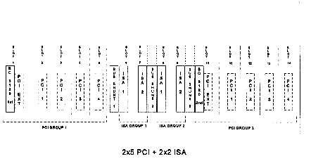
Figure 1
2x5 PCI + 2x2 ISA MIB
Legend:
8 = Shunt installed
0 = Shunt not installed
NOTE: This backplane supports a maximum of two shunts at a time. Installing three shunts to create one bus constitutes an illegal configuration that is not supported by Cubix Corporation.
Table 1
2x5 + 2x2 MIB Configurations
Bus Shunt |
Configuration |
||
1 |
2 |
3 |
|
| 0 | 0 | 0 | Four separate buses: Slot 1 supports the BC processor and extender card Slots 2 + 5 support one PCI adapter each ISA Group 1 consisting of ISA slots 6 and 7 to support one BC and ISA adapter ISA Group 2 consisting of ISA slots 8 and 9 to support one BC and ISA adapter PCI Group 2 consisting of five slots: Slot 10 supports the BC processor and extender card Slots 11 + 14 support one PCI adapter each |
| 8 | 0 | 8 | Two separate buses: PCI Group 2 and ISA Group 2 comprise the second bus to support one BC with extender card and up to four PCI adapters and two ISA adapters |
| 8 | 8 | 0 | Two separate buses: PCI Group 2 is the second bus and can support one BC with extender card and up to four PCI adapters |
| 0 | 8 | 8 | Two separate buses: PCI Group 2 and ISA Group 1 and 2 comprise the second bus which supports one BC with extender card and up to four PCI adapters and four ISA adapters |
| 0 | 8 | 0 | Three separate buses: ISA Group 1 and 2 combined creates the second bus to support one BC and three ISA adapters PCI Group 2 is the third bus and can support one BC and extender card plus four PCI adapters |
| 8 | 0 | 0 | Three separate buses: and can support four PCI adapters and two ISA adapters ISA Group 2 is the second bus which supports one BC and one ISA adapter PCI Group 2 is the third bus and can support one BC with extender card and four PCI adapters |
| 0 | 0 | 8 | Three separate buses: ISA Group 1 is the second bus and can support one BC and one ISA adapter PCI Group 2 shunted to ISA Group 2 creates the third bus to support one BC with extender card and four PCI adapters and two ISA adapters |
4x3 PCI MIB
Used only with the passive PCI bus extender card, the 4x3 MIB provides four groups of three slots each. Cubix offers two versions of the 4x3 MIB which are functionally the same but, provide different physical placement of the (slot) connectors. Figures 2 and 3 illustrate the differences. Each slot group supports one BC 5090/5120/5150SE or SP processor with extender card and up to two PCI adapters or, one ISA adapter or, a combination of one ISA and one PCI adapter on the same bus. Neither 4x3 MIB is field configurable.
Note that these two versions do not use the same sheet metal so, if a replacement is required be sure to specify the correct assembly number. The assembly number is printed on the front of the circuit board as shown in Figures 2 and 3.
In Addition . . .
A BC 5090/5120/5150SP will intrude on the adjacent ISA or PCI slot depending on the height of the BC’s SIMM modules. An intrusion of up to 2-inches is possible.
For the A04970 model only: A BC 5090/5120/5150SP in group 4 cannot accept a SIMM module greater that 1.25-inches. SIMM modules higher than this touch the metal chassis.
If a bus segment requires ISA only (no PCI interface), the BC processor can be installed without the PCI extender card.
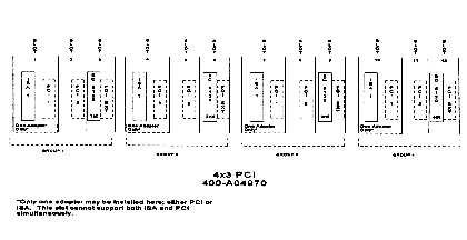
Figure 2
4x3 PCI MIB - Assembly A04970
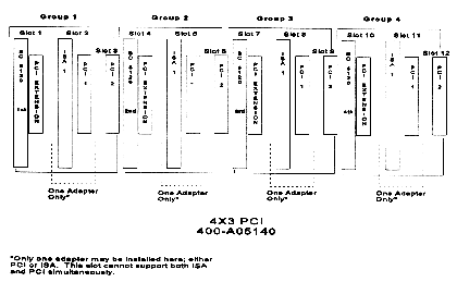
Figure 3
4x3 PCI MIB - Assembly 5140
7x2 PCI MIB
Used only with the passive PCI bus extender card, this MIB provides seven groups of two slots each (see Figure 4). The 7x2 MIB supports up to seven BC 5090/5120/5150SE or SP processors (with PCI extension card if PCI adapter is being installed), and one ISA or PCI adapter per BC. The 7x2 PCI MIB is NOT field configurable.
In Addition . . .
A BC 5090/5120/5150SP will intrude on the adjacent ISA or PCI slot depending on the height of the BC’s SIMM modules. An intrusion of up to 2-inches is possible.
If a bus segment requires ISA only (no PCI interface), the BC processor can be installed without the PCI extender card.
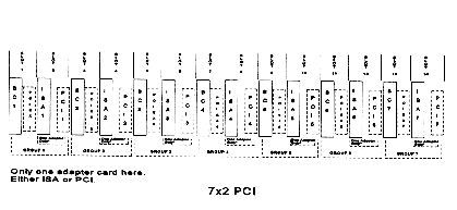
Figure 4
7x2 PCI MIB
BC 5120/5150E Power Requirements
The BC 5120/5150E are Cubix’s new 120 MHZ Pentium® processor-based EISA boards with a 32-bit SCSI interface, and up to 128 MB of RAM. When determining the total power requirements for an ERS/FT II subsystem supporting one or more BC 5120/5150Es, use the following information in conjunction with Table B-2, Cubix Product Power Requirements (Watts). This table is located in Appendix B, of DOC 805C, Series II Subsystems User’s Guide.
BC 5120E Power Requirements in Watts
| Device | +5V | +12V | -12V |
| BC 5120E (equipped with 8 to 64 MB RAM) | 28.05 | .6 | .6 |
| BC 5120E (equipped with 128 MB RAM) | 36.25 | .6 | .6 |
| BC 5150E (equipped with 8 to 64 MB RAM) | 27.5 | .6 | .6 |
| BC 5150E (equipped with 128 MB RAM) | 35.0 | .6 | .6 |
ERS/FT II Electronic Over Current Protection
Electronic over current protection is available on ERS/FT II subsystems equipped with PCI MIBs (backplanes).
Rather than fusing each ISA/PCI slot, circuits designed as circuit breakers are used to protect each slot group segment from a current overload.
LED Indicators
Amber LEDs are located on the backplane at the back of the system centered on each slot group. When an over current fault occurs, group power is turned off and the amber LED associated with the slot group on which the over current was detected will be lit. If one or more slot groups are shunted together, the entire group is turned off. The amber LED shows which of the slot groups detected the overload.
Resetting the Slot Group
When the overload condition has been cleared, the affected slot group must be reset by cycling its group power off then on again.
Note! Recycle power only after the overload condition has been cleared.
To cycle the group power, use a pointed device (such as a pen) to press the group power push-button inward. The push-button functions as a toggle, turning power On if it is already Off or, Off if already On. Refer to Chapter 3 in DOC 805C, Series II Subsystems User’s Guide for additional information about the Group Power function.
Current Trip Points , PCI MIBs
Current trip points (the point at which the slot group shuts down), for the three PCI MIBs are listed in Table 2.
Table 2
Trip Points for PCI MIBs
MIB |
Current Trip Points for each 2-slot group |
|||
| +5VDC | +12VDC | -12VDC | -5VDC | |
| 2x5 + 2x2 |
18.5 Amps +/- 18 % 13.5 Amps +/- 18% |
7.5 Amps +/- 18% 3.75 Amps +/- 18% |
.475 Amps +/- 15% .36 Amps +/- 15% |
.14 Amps +/- 15% .14 Amps +/- 15% |
| 4x3 | 15.5 Amps +/- 18 % | 4.5 Amps +/- 18% | .36 Amps +/- 15% | .14 Amps +/- 15% |
| 7x2 | 13.5 Amps +/- 18% |
3.75 Amps +/- 18% | .36 Amps +/- 15% | .14 Amps +/- 15% |
Note: +3.3VDC at 1.5 Amps is available for the PCI slots. +3.3VDC is generated from the+5VDC. When calculating the total +5VDC current, include the total +3.3VDC current. For example, if +5VDC=5A and +3.3VDC=1A, the total +5VDC current is 6A. Note that the +3.3VDC is short circuit limited to 2 Amps. A short on the +3.3VDC causes an over current trip only if the total +5VDC current trip point is exceeded.
Current Trip Points , ISA 8x2 MIB
The current trip points for the ISA 8x2 MIB (also referred to as the ISA 8x2 Backplane),on page 5-10 of the Series II Subsystems User Guide has changed from -12VDC at .24 Amps +/- 15% for each 2-slot group to -12VDC at .36 Amps +/- 15% for each 2-slot group.
New Power On Self Test Error Code
| Hexadecimal Error Code | Test Description | Status |
| A2 | Backplane test. At power on, an
ERS/FT II checks to "see" which backplane is installed. This error is generated
when an unrecognizable backplane is detected. Note that this error may also be the result
of faulty relays. If a 14+2 backplane is installed, this code always occurs during startup (the 14+2 is not equipped with relays). This is considered normal and performance is not affected. |
Nonfatal |
Note: If auto-configuration was initiated during the five-second countdown at power on, normal power up could take up to 90 seconds to complete. If auto-configuration was skipped, the process takes approximately 15 seconds.
48VDC Power Supply
Cubix now supplies an ERS/FT II subsystem with a -48VDC power supply. All specifications listed in Appendix A and Appendix B of the Series II User’s Guide apply except for the following:
Power Supply Model 403-A0345
-48VDC (-40V to -60V acceptable range) ................... 13ADC
Also note that the AC Power On indicator referenced in the "Rear Panel Connections" and "ERS/FT Rear Panel Only" sections on page A - 4 of the Series II User’s Guide, DOES NOT apply to subsystems equipped with the -48VDC power supply.
I/O Panel
The I/O Panel is located on the left when viewing the rear of the subsystem (see Figure 5). The connectors on the I/O panel are explained below. Instructions for using these connectors to install the subsystem are in the Series II User’s Guide, Chapter 2 - Subsystem Installation.
+ = Positive Input (-48VDC)
- = Negative Input (-48VDC)
O = Chassis Ground
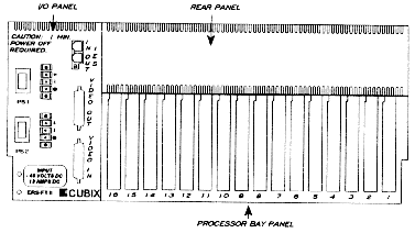
Figure 5
-48VDC Power Supply - ERS/FT II Rear panel
Mounting a CD-ROM in a Series II Subsystem
With the use of a special bracket and matching front panel, a CD-ROM may be mounted in a Cubix Series II Subsystem, and connected to one of the BC Series boards inside. This configuration allows for seven third-height hard drives, five of which are ‘hot-swappable’, that is, each drive can be removed after powering down the backplane segment that has the BC Series board to which the drive is connected.
To change the CD-ROM, the floppy drive, or either of the two hard drives mounted in the CD-ROM mounting bracket, power down the ERS/FT II. Remove the front cover as shown in Figure 6. The front cover is attached to the chassis by six #6 flat-head screws, three on each side. Remove all six screws.
The top tie-down bracket is removed by twisting the screw mounted on the left side until it is loose. Then, tilt the bracket upwards until the CD-ROM mounting bracket can be removed from the slot on the right. The bracket assembly can then be lifted out of the drive bay. Detach all necessary cables before proceeding with drive removal. Drives are mounted to the CD-ROM mounting brackets with four screws each, two on each side. The drive can then be slid out from its position in the CD-ROM mounting bracket. To replace the drive, follow these instructions in reverse order.
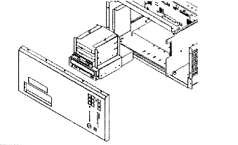
Figure 6
CD-ROM Mounting
This document, and all Web contents,
Copyright © 1997 by Cubix Corp., Carson City, NV, USA.