WorldDesk Commuter
Quick Reference Guide
Frame Type Indicator
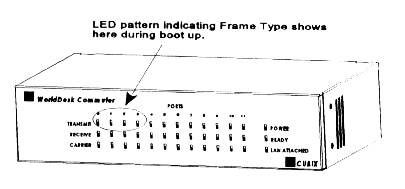
During initial boot up, WorldDesk Commuter automatically detects the frame type in use on the network. Once detected, the frame type is locked in as default and displayed via one of the first four front panel LEDs (see Figure 1 - 2). Each time WorldDesk Commuter is booted, the frame type displays via these LEDS. The LED/Frame Type association is shown below:
| If this LED lights | The Frame Type is. . . |
| 0 | Ethernet 802.2 |
| 1 | Ethernet SNAP |
| 2 | Ethernet 802.3 |
| 3 | Ethernet II |
The frame type may be changed at any time via WorldDesk Manager’s "Server/Configuration" menu options. Refer to the WorldDesk System Administrator’s Guide for information on how to use WorldDesk Manager software.

Figure 1-2, Front Panel View
Table 1 - 1, Front Panel LEDs
| LED | Definition |
| Transmit | A green LED indicates the corresponding port is sending data. |
| Receive | A green LED indicates the corresponding port is receiving data. |
| Carrier | A green LED indicates an active modem connection on the corresponding port. |
| Power | A green LED indicates power is applied to WorldDesk Commuter. |
| Ready | A green LED flashes at one second intervals during WorldDesk Commuter operation. If no LED activity occurs when Power LED is lit, refer to Troubleshooting. |
| LAN Attached | A steady green LED indicates the 10BASE-T network link is good. |
| Note: If after power on, a LED does not light when appropriate, refer to Chapter 4, Troubleshooting (in this manual) or the WorldDesk System Administrator’s Guide for corrective action. If the problem persists, contact Cubix for technical support. | |
Rear Panel View
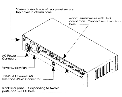
Figure 1 - 3 illustrates the external modem version of WorldDesk Commuter. Rear panel components include the AC power cord connector, power supply fan, Ethernet LAN interface, and serial (COM) port connections 0-5. Internal PC Card modem connections are shown in Figure 1 - 4.
Port Locations and Numbering
When viewing serial or PC Card modem connections at the rear of WorldDesk Commuter, note that the top module is "first" and the bottom module is "second." Port numbering for the serial module begins with the top module where Port 0 is the left-most port and Port 5 the right-most port. If a second module is installed, it is always the bottom module and numbered 6 through 11 with the left-most port being Port 6.
When viewing the PC Card modem module note that there are two PC Card modems per panel cutout. For the first PC Card modem module, PC Card modem connectors are numbered 0 through 5. Connectors 0 and 1 are located at the left panel cutout, 2 and 3 at the center cutout, and 4 and 5 at the right cutout. If a second PC Card module is installed, numbering begins with 6 and 7 for the left cutout and ends with 10 and 11 for the right cutout.

Figure 1-3, Rear Panel Components and Serial Port Module
Figure 1-4, Rear Panel Components and PC Card Modem Module
Systems | Circuit Boards | Other Products | Software | Hardware Identifier
Other Vendors | Technical Notes | Downloads | Search | Support Home Page
This document, and all
Web Site contents, Copyright ©
2000 by Cubix Corp., Carson City, NV, USA.