 |
|
|
|
Density 1200 System
Chapter 2 - Installation
Unpacking the Density System
1. Inspect the shipping box for damage.
2. Remove the Density Series system from the shipping container, and place on a secure working surface.
Installation of a Density System into a Cabinet
WARNING!
Care should be taken when installing a Density Series system. The weight of a fully loaded Density Series enclosure (approx. 130 lbs.) placed on fully extended rails may cause the cabinet to tip forward. The cabinet should be secured before installing the enclosure.
The Density Series system is a rack-mount enclosure designed to be installed in a Cubix System 1010 cabinet or other RETMA-compatible 19" wide equipment rack.
1. Remove the middle and rear sliding rails from the sides of the Density System.
2. With the middle rails still inserted into the rear rails, mount them into the cabinet using the four brackets provided.
VKM (Video, Keyboard and Mouse)-External Cabling
These devices may be shared between multiple systems. This is accomplished by daisy-chaining the systems together with DB-25 male to male cables attached to the VKM connectors which are located on the back of the Mux/IES board (see Figure 8). A maximum number of eight Density chassis may be VKM connected.
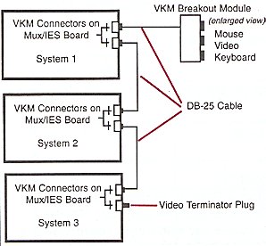 |
Connect the unused VKM connector on the first system to
the Video/Keyboard/ Mouse Breakout Module, using DB-25 cabling. (VKM Module can be mounted
in the top of the System 1010 cabinet or wherever it is convenient.) If the monitor, keyboard, and mouse are not already connected to the breakout module, route the cables for these devices into the cabinet via the access hole in the top cover and connect the cables to the breakout module. Connect the video terminator plug to the unused VKM connectors on the last system. |
Note: JP2 through JP9 are available for customers who wish to disable VKM for selected groups (see Figure 4) and use their own external VKM. For more information contact Customer Service.
Input Power
The Density Series systems uses three power supplies operating in parallel. Two of the three are required to power the system. Therefore if any one of the three fail, system integrity is maintained. Input power is provided via a single power cord shipped with your system.
The following type of power cord is supplied:
| (Domestic 120Vac) | SVT,SJT | 125V/13A | AWG16/3 |
| (European 240Vac) | SVT,SJT | 250V/10A | 1mm2/3 |
Warnings Pertaining to Internal Access
The following Sections require access to the Density CPU bay and power supply areas which are restricted to service personnel only. Therefore, these warnings apply to each section.
CAUTION!
CONTAINS HAZARDOUS VOLTAGES, NO USER
SERVICEABLE PARTS INSIDE
ATTENTION!
TENSION DANGEREUSE, L’APPAREIL NE COMPORTE AUUN
ELEMENT QUE L’UTILISATEUR PULSSE REPARER
ACHTUNG!
GEFAHRLICHE STROMSPANNUNGEN!
KEIN BENUTZER ZUGANGLICHE TEILE!
Mux Option Switch (S1)
Mux options determine the behavior of the Density system when the console is locked. The options are set with an 8 position DIP switch (S1) on the Multiplexor/ IES board (see Figure 4 for the switch location). Changing the following Mux option switches must be followed by a power-on sequence of the Density chassis. Positions 1 through 4 are Mux option selections. Positions 5 through 8 should not change, but remain consistent with Table 3, factory default settings.
Table 2 Mux Option Switch Definitions (S1)
| Option | 1 | 2 | 3 | 4 |
| Video Only - If this option is enabled and the
console is locked, all of the muxed devices except for the monitor are disabled. The
monitor remains functional on the channel that was selected at the time the lock occurred.
This is a useful feature if there is a management application running on one of the computers in the system. By selecting the processor group containing this computer before locking the console, the screen on the management application can be monitored. However, the other muxed devices and the console functions remain disabled, thus eliminating the possibility of unauthorized intervention. |
off | on | on | on |
| Monitor/Keyboard/Mouse/Reset - If this option is
enabled and the console is locked, the only muxed device that will be disabled is the
floppy disk drive. The monitor, keyboard, and mouse will continue to function on the
selected channel. In addition, the "Reset Selected Group" pushbutton on the front panel of the system will remain functional, allowing an operator to reset the computer selected as the current group at the time the console is locked. The "Group Select" pushbuttons are disabled, thus preventing the operator from resetting another processor group. This is a useful feature if the system administrator wants to prevent use of the floppy drive for security purposes. |
on | off | on | on |
| Floppy Channel 1 - If this option is enabled and either the console is locked or the system is disabled, the floppy drive will be connected to the first mux channel, regardless of the processor group currently selected. | on | on | off | on |
| Master Console Key lock - Systems may be
connected by daisy-chaining them via the VKM connectors on the rear panel of the
Multiplexor/IES board. This connection is required to share a monitor, keyboard, and mouse
between as many as eight systems. If the Master Console Key lock option is enabled, the system will function as a "master console." If the master console is locked, the consoles of all systems connected to the master console are locked, regardless of the position of the key switch on their front panels. A Density Series system will not function as a master console if the system is turned off. A Density Series system with the Master Console Key lock option enabled will remain the master console through a power failure. More than one system in a daisy-chain can have the Master Console Key lock option enabled. If this is the case, it is necessary to unlock the key switch on the front panel of each system with the option enabled. As long as the key switch remains in the locked position on any system with the master key lock option enabled, all of the systems in the daisy-chain will remain locked. |
on | on | on | off |
No Mux Options Enabled - The option switches
override one or more of the effects of locking the console using the console Mux. The
console Mux is explained in Chapter 3 of this manual. If none of the key lock options are
enabled, locking the console disables the following functions:
|
on | on | on | on |
Table 3 Factory Default Settings for Switch 1
| 1 | 2 | 3 | 4 | 5 | 6 | 7 | 8 | |
| S1 | ON | ON | ON | ON | ON | ON | OFF | OFF |
Integrating Density Series into a GlobalVision Management System
The Density Series system may be managed by an existing GlobalVision (version 2.15 or greater) management system operating in a Cubix ERS/FT II or PowerSMP series chassis. The following section will provide the configuration necessary to integrate the Density system into the existing management system.
Configuring IES Data Highway Address
The Density Series system includes an out-of-band Data Highway which connects the chassis Intelligent Environmental Sensor (IES) to a GlobalVision management
processor (refer to the GlobalVision Management System User’s Guide). This data highway can be daisy-chained between systems to allow management of up to 31 enclosures from a single GlobalVision management processor.
Each chassis connected to the IES data highway must be assigned a unique data
highway address. The GlobalVision console application uses this address to identify and communicate with each IES module. Valid IES addresses range from 1 to 31.
The factory default address of the IES is 1.
The Density Series IES Data Highway is integrated onto the Mux/IES board. The address of the IES is determined by an 8-position DIP switch (S2) located on the top edge of the board (see Figure 4 for switch location). Each chassis that is added is assigned the next address number in the sequence. S2 must be set accordingly. No two chassis can have the same address.
Table 4 contains valid IES address switch configurations for 31 chassis.
Table 4 IES Address Switch Configuration (S2)
DIP Switch Position |
||||||||
Address |
1 |
2 |
3 |
4 |
5 |
6 |
7 |
8 |
1 |
OFF |
ON |
ON |
ON |
ON |
ON |
ON |
ON |
2 |
ON |
OFF |
ON |
ON |
ON |
ON |
ON |
ON |
3 |
OFF |
OFF |
ON |
ON |
ON |
ON |
ON |
ON |
4 |
ON |
ON |
OFF |
ON |
ON |
ON |
ON |
ON |
5 |
OFF |
ON |
OFF |
ON |
ON |
ON |
ON |
ON |
6 |
ON |
OFF |
OFF |
ON |
ON |
ON |
ON |
ON |
7 |
OFF |
OFF |
OFF |
ON |
ON |
ON |
ON |
ON |
8 |
ON |
ON |
ON |
OFF |
ON |
ON |
ON |
ON |
9 |
OFF |
ON |
ON |
OFF |
ON |
ON |
ON |
ON |
10 |
ON |
OFF |
ON |
OFF |
ON |
ON |
ON |
ON |
11 |
OFF |
OFF |
ON |
OFF |
ON |
ON |
ON |
ON |
12 |
ON |
ON |
OFF |
OFF |
ON |
ON |
ON |
ON |
13 |
OFF |
ON |
OFF |
OFF |
ON |
ON |
ON |
ON |
14 |
ON |
OFF |
OFF |
OFF |
ON |
ON |
ON |
ON |
15 |
OFF |
OFF |
OFF |
OFF |
ON |
ON |
ON |
ON |
16 |
ON |
ON |
ON |
ON |
OFF |
ON |
ON |
ON |
17 |
OFF |
ON |
ON |
ON |
OFF |
ON |
ON |
ON |
18 |
ON |
OFF |
ON |
ON |
OFF |
ON |
ON |
ON |
19 |
OFF |
OFF |
ON |
ON |
OFF |
ON |
ON |
ON |
20 |
ON |
ON |
OFF |
ON |
OFF |
ON |
ON |
ON |
21 |
OFF |
ON |
OFF |
ON |
OFF |
ON |
ON |
ON |
22 |
ON |
OFF |
OFF |
ON |
OFF |
ON |
ON |
ON |
23 |
OFF |
OFF |
OFF |
ON |
OFF |
ON |
ON |
ON |
24 |
ON |
ON |
ON |
OFF |
OFF |
ON |
ON |
ON |
25 |
OFF |
ON |
ON |
OFF |
OFF |
ON |
ON |
ON |
26 |
ON |
OFF |
ON |
OFF |
OFF |
ON |
ON |
ON |
27 |
OFF |
OFF |
ON |
OFF |
OFF |
ON |
ON |
ON |
28 |
ON |
ON |
OFF |
OFF |
OFF |
ON |
ON |
ON |
29 |
OFF |
ON |
OFF |
OFF |
OFF |
ON |
ON |
ON |
30 |
ON |
OFF |
OFF |
OFF |
OFF |
ON |
ON |
ON |
31 |
OFF |
OFF |
OFF |
OFF |
OFF |
ON |
ON |
ON |
IES Data Highway Cable
After setting the IES address, connect the Density Series system to the Cubix data highway.
NOTE!
While similar to an RJ-11 telephone station cable, the data highway cable is wired as a "straight through" cable and cannot be replaced using a standard telephone cable. The cable will have a white sticker marked "Cubix IES Module Only."
1. Connect one end of the data highway cable to either of the Out-of-Band Data Highway Connections found on the Mux/IES board (see Figure 3).
2. If this system is not the last device in the chain, connect the other Out-of-Band Data Highway Connection to the next device. Set switch S3 (see Figure 4 for switch location) to the OFF position. The switch is OFF when it is pointing to the left when viewed from the rear of the Density Series system.
3. If this system is the last device in the chain, terminate the highway by setting switch S3 to the ON position. The switch is ON when it is pointing to the right when viewed from the rear of the Density system.
Data Highway Adapter
Density Series servers may optionally be used as the GlobalVision Console for a group of Cubix enclosures. The server which will act as the GlobalVision Console requires installation of a Data Highway Adapter to the COM2 header. This adapter provides an
interface point for the GlobalVision console processor to collect IES data from all
chassis in the data highway chain.
Perform the following instructions to install a data highway adapter on a Density Series server.
1. Remove the cover plate for IES Data Highway Adapter located in the rear of the DP Density chassis. (See Figure 3. Location may vary on other chassis.)
2. Attach the 10-pin ribbon cable of the Data Highway Adapter to the COM2 header:
3. Secure the Data Highway Adapter board in the cut out area. (The Data Highway Adapter assembly consists of one A4212 board, ribbon cable, two brackets and two screws.)
Installing Additional Server Boards (DP or SP Series)
The following instructions provide general installation instructions for Density Series compatible server boards. Refer to the appropriate manual supplied with the processor board for detailed configuration instructions.
CAUTION!
Group power must be off before installing any Cubix processors, peripheral boards, or third-party peripheral cards. Failure to follow this warning may result in damage to the Density Series system and
boards being installed.
1. At the front console, select and turn power off to the group location where you intend to install the server board (refer to Chapter 3 for front console operation instructions).
2. If a hard-drive is installed in the group hard drive slot, remove the hard drive and the SP or DP board.
3. Configure the switch and jumper settings on the board being installed. (Refer to the Quick Reference Guide accompanying the board.)
4. Insert the board into the group slot ensuring the card interface tabs are aligned with the center of the slot.
5. Seat the processor card into its slot by firmly pressing on the top of the card with the palm of your hand.
6. Install the hard drive assembly into the appropriate hard drive bay located in the front of the Density closure (Figure 2). The hard drive assembly will fit into the hard drive interface of the I/O board. Make sure it is seated.
7. At the front console apply power to the processor group.
Installing/Replacing Power Supply
Density Series uses three hot-swappable load-sharing Power Supplies in a redundant fault-tolerant n+1 configuration. Redundant cooling systems provide added resilience.
CAUTION!
The Density System requires two power supplies to provide power to server groups. Make certain there are two Power Supply switches “on” before removing the third Power Supply.
The steps for replacing a Power Supply are quite simple. Refer to Figure 3 for location of Power Supplies.
1. The power supply that does not have the green light on is the power supply that needs replacement.
2. Turn the switch to an “off” position on the Power Supply to be removed.
3. Loosen the two captive screws and grasp the Power Supply handle. Pull the Power Supply out of the chassis.
4. Insert the replacement Power Supply.
5. Secure the captive screws.
6. Turn the new Power Supply “on”.
This document, and all Web contents, Copyright © 2000 by Cubix Corp., Carson City, NV, USA.