 |
|
|
|
Density 1200 System
Chapter 1 - Introduction
The Cubix Density enclosure houses multiple server-class Intel“ compatible computers neatly and efficiently in a single, rack-mountable drawer. The Density Series can support both single and dual SMP processor boards through three standard backplane options*:
*Other backplane options are available. Consult your sales representative for more information.
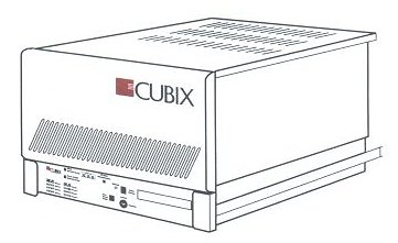
Figure 1 Density Series System
Overview of Density Series System
The Density Series system is designed for the purpose of computer consolidation. Cubix equipment solves the problems associated with space-constrained backroom computing centers. Figures 2 and 3 on the following page show the arrangement of a consolidated Density system.
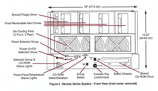
Figure 2 Density Series System - Front View (front cover removed)
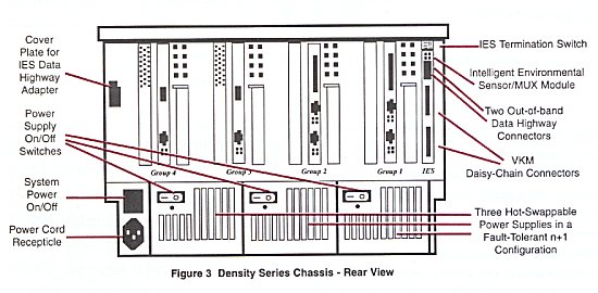
Figure 3 Density Series Chassis - Rear View
The Intelligent Environmental Sensor (IES) is integrated into a Multiplexor/IES Module board which is installed in a backplane slot (IES slot, Figure 3) of the Density Series system. The IES monitors system and processor health, and functions as an interface between the Density Series system and the Cubix IES Supervisory System. The IES Supervisory System provides SNMP instrumentation and integration with the Cubix GlobalVision management application.
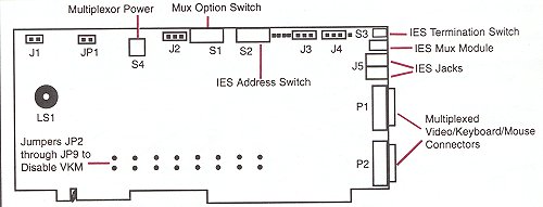
Figure 4 Multiplexor/IES Board Layout (Assembly 400-A06191)
Passive Backplane Options
The Density Series enclosure is assembled in one of the following passive backplane configurations:
4X DP (Figure 5)
8X SP (Figure 6)
2X DP + 4X SP (Figure 7)
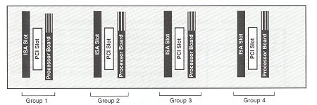
Figure 5 - 4x DP Density Series Backplane
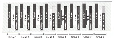
Figure 6 - 8x2 Density Series Single-Processor Backplane
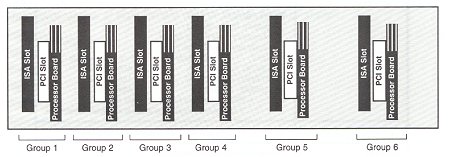
Figure 7 - 2x DP+4x SP Density Series Backplane
Technical Specifications
Table 1 Density Series System Technical Specifications
| System Architecture | x86 multiserver class managed systems. |
| Hard-Disk-Drives | Up to 12 third-height, vertically mounted drives mounted in single, dual or triple drive-mounting assemblies. |
| Floppy Drive | One shared third-height, 3.5" vertically mounted, 1.44MByte capacity floppy disk drive. |
| CD-ROM Drive | One shared and independently switched CD-ROM drive. |
| Dimensions | RETMA-compatible rackmount enclosure - 19" wide x 12.25" high (7U) x 23.25" deep. Faceplate 17" wide x 12.25" high. |
| Integrated Multiplexor | Shared support for: VGA Video, PS/2-compatible keyboard, PS/2-compatible mouse, Floppy drive, CD-ROM drive, Environmental monitoring, and Server status monitoring. |
| Front-Panel Controls | Key lock multiplexor/video enable/disable, Group processor reset, Group power on/off, Group select, CD-ROM select and Select Chassis. |
| Front-Panel Status | Power/Fan/Temperature Displays Selected Group for Video/Keyboard/Mouse control Selected Group for CD assignment "Selected" LED for Chassis activation |
| Power Supply | Three redundant, load-sharing (n+1) power supplies per
system Hot-swappable (minimum 2 power supplies required to support system operation) Power on indicator Input power
Power Ratings System Power Rating Maximum Total Power 600W Volts Amps Max/Peak Power Max/Peak +5VDC 90A/90A 450W/450W * + 12V @ 20Amps for 10 seconds maximum. If sustained longer, the system will over-current trip. |
| Operating Environment | 0 - 40° C temperature 5% - 80% noncondensing humidity |
| Warranty | 3-year warranty with registration (parts and labor, return to manufacturer) |
This document, and all Web contents, Copyright © 2000 by Cubix Corp., Carson City, NV, USA.