BCVision
Chapter 3 - BCVision
In installations equipped with CMS or another SNMP management system, the BC Supervisor should be dedicated to running BCVision. This ensures that alarms are reported to the SNMP system at the time they occur. It also makes IES Supervisory System information available to the management console.
In installations not equipped with CMS or another SNMP management system, dedicating the BC Supervisor to running BCVision is still recommended. A monitor should also be dedicated to the BC Supervisor, and this monitor should be placed in a location visible to the network administrator. This allows alarms displayed by BCVision to be reported to the administrator at the time they occur.
If BCVision is not running on the BC Supervisor, SNMP support is disabled. Since CMS uses SNMP for its network communications, CMS will not be able to manage this IES Supervisory System. No IES Supervisory System information or alarms will be reported to the SNMP management system until BCVision is invoked. However, each IES continues to perform the monitoring and control functions, even when BCVision is not running. Therefore, all IES Supervisory System functions are still performed, including monitoring the subsystem environment and performing the CPR function (if enabled). If an alarm occurs, the speaker will sound and a LED will be illuminated. The next time BCVision is invoked alarms will be displayed (and SNMP traps generated) for any faults that occurred while BCVision was not running.
To run BCVision, the files BCVISION.DAT, BCVISION.HLP, and BCMASTER.EXE must reside in the same directory as BCVISION.EXE. These files are usually installed on the hard drive of the BC Supervisor, although they may be run from a network file server or floppy drive. The BCMaster TSR must be loaded before BCVision is invoked.
It is recommended that BCVision automatically execute each time the BC Supervisor is booted. This requires adding the following lines to the AUTOEXEC.BAT file:
bcmaster
bcvision
Note! If network communications are required, VLM.EXE must be executed before BCMASTER.EXE is loaded.
These commands may alternatively be entered at the DOS command line. Remember the loading order described in Chapter 2:
If network communications and SNMP support are not required, only BCMASTER.EXE and BCVISION need to be invoked.LSL.COM
<DRIVER.COM>
<IPXODI.COM> or <TCPIP.EXE>
VLM.EXE
<STPIPX.COM> or <STPUDP.COM>
BCMASTER.EXE
BCVISION.EXE
Password
Before you are allowed to access any BCVision functions, a screen similar to the one illustrated in Figure 3-1 is displayed. BCVision will not require a password until one is configured.
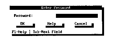
Figure 3-1
Password Entry
IES Status Screen
Once an appropriate password has been entered, BCVision will display a status screen similar to the one illustrated in Figure 3-2. This screen displays each IES found on the Cubix data highway. However, if this is the first time BCVision has been invoked, no IES will be listed. The user is required to configure each IES through BCVision before it appears on this display.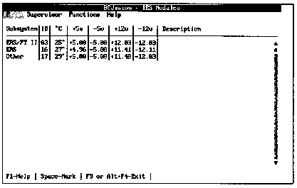
Figure 3-2
IES Status Screen
To configure an IES not listed on the display, run the Setup option as described in the Functions Menu section of this chapter.
The screen displays the subsystem in which the IES is installed, the data highway ID of each IES found, the temperature of the subsystem containing each IES, the current voltages of each subsystem, and a description associated with each IES.
The ID refers to the data highway identification of each IES as determined by a hardware switch setting. If the subsystem is an ERS/FT II, the switch is located on the subsystem. Otherwise, the switch is located on the IES module itself. These ID numbers must be unique.
The temperature is displayed in degrees Celsius and reflects the temperature of the subsystem in which the IES is located.
The +12, -12, +5, and -5 voltages are displayed. These values reflect the voltage levels on the bus in the subsystem containing the IES.
Note! Since SafeStor/FT does not support -12V or -5V levels, these values are shown as "N/A."
The Description is a user defined text description and may contain up to thirty-one characters to describe the IES or subsystem in which the IES resides.
If a fault condition exists in a subsystem, the corresponding IES displays in red. The active alarms on an IES are listed on the IES Detail Display, which is accessible from the Functions Menu.
From the IES Status Screen, the following functions are available:
Exit BCVision
To exit BCVision, press <Alt>+<F4> or exit through the File Menu.
Help
Press <F1> to view help information describing BCVision.
Mark
Some Functions Menu options operate on Intelligent Environmental Sensors (IES) that are "marked". To mark a sensor, use the arrow keys to highlight the IES to be marked, and press the <Space Bar>. If an alarm condition exists, a marked IES displays on a black background. If not, it displays on a dark blue background. To unmark an IES, press the <Space Bar> again. The color returns to its previous state.
Functions Menu operations may be performed on multiple subsystems simultaneously. This is achieved by marking each IES to which the function applies then executing the function. For example, assume that all sensors are marked and the maximum temperature threshold is set to 60 degrees. The new threshold will be applied to all of the sensors, causing BCVision to generate a temperature alarm only if the temperature in one of the subsystems exceeds 60 degrees Celsius.
The ability to Mark All sensors is available under the Functions Menu. This is a convenient way of performing a single function for all of the subsystems in the IES Supervisory System.
Access Menu OptionsThe following keystrokes will provide access to the main menu options:
Alt Pressing this key moves the cursor to the menu bar. Arrow keys may then be used to select a menu option.
Alt+F Pressing the "F" key while holding the <Alt> button accesses the File Menu.
Alt+S Pressing the "S" key while holding the <Alt> button accesses the Supervisor Menu.
Alt+N Pressing the "N" key while holding the <Alt> button accesses the Functions Menu.
Alt+H Pressing the "H" key while holding the <Alt> button accesses the Help Menu.
File Menu
The File Menu allows the user to exit BCVision and return to DOS. Press Esc to exit the menu. Supervisor Menu The options available from the Supervisor Menu include:Press Esc to exit the menu.
Set Password
Use the Set Password option to create or modify a BCVision password.
Prompts to enter existing and new passwords are displayed. This added layer of security prevents unauthorized users from modifying the system password. Enter the current password if one exists.
Enter the new password. Verify the new password by entering it a second time. Once the same password is entered twice, it becomes the new BCVision password.
A password may contain any printable ASCII character (20 - 7F hexadecimal), and are not case sensitive: "a" is interpreted to be the same as "A".
Enable/Disable Confirmation
Throughout BCVision, execution of any critical function is preceded by a confirmation message. For example, if a user instructs BCVision to reset a BC processor, BCVision displays a message requesting the user to verify that the reset is to be performed before the command is actually executed. This allows the user to prevent accidental functions from disrupting the system.
Functions protected with the confirmation message include:
Confirmation messages may be enabled or disabled within BCVision. To enable or disable the confirmation messages, select the Enable/Disable Confirmation option from the Supervisor Menu.
Enable/Disable SNMP Support
With SNMP support enabled, BCVision attempts to locate an SNMP agent on the workstation. If BCVision does not find a SNMP agent, an error message is displayed. If SNMP support is not required, the support can be disabled and the error will be avoided.
SNMP support is enabled by default after initial installation of the IES Supervisory System. Therefore, the SNMP error message may occur the first time BCVision is run, but will not occur after SNMP support is disabled.
To enable or disable SNMP support, select the Enable/Disable SNMP Support option from the Supervisor Menu.
Enable/Disable Alarm Notification
BCVision provides an Enable/Disable capability for system alarms that can be used to enable or disable alarm notification messages. While disabling alarm notification turns off warning messages at the IES supervisory level, it does not disable alarms to other management systems such as CMS.
To enable or disable alarm notification, select the Enable/Disable Alarm Notification option from the Supervisor Menu. With alarm notification enabled, any of the following conditions generate an audible alarm, illuminate the appropriate LED, and display a message on the BCVision console.
If the alarm notification feature is disabled, the message "Alarms Disabled" appears and remains in the lower right corner of the console screen. To close a Warning Screen, BCVision provides three options: "Acknowledge," "Disable Notification," or "OK." "Acknowledge" closes the warning screen and enables the system to continue alarm notification whenever an alarm condition occurs. "Disable Notification" closes the warning screen, displays the "Alarms Disabled" message, and prevents further alarm notifications. If at a later time, you want to enable notification, use Enable/Disable Alarm Notification from the Supervisor Menu. Some warning screens provide an "OK" option only. Clicking on the OK button or pressing <Enter> implies acknowledgment and the system continues in the same manner as when Acknowledge is selected.
Set Refresh Rate
The refresh rate determines how often BCVision polls each IES over the data highway. The rate at which the BCVision display is refreshed is also set to this value.
To modify the refresh rate, select Set Refresh Rate from the Supervisor Menu. The rate may range from 1 to 60 seconds. The default is two seconds.
Set SNMP Status Trap Rate
If a trap target address was configured in the NET.CFG file on the BC Supervisor during installation, BCVision periodically generates a standard SNMP trap to the specified address. This trap is intended for receipt by a CMS console. If CMS is not installed, set the SNMP Status Trap Rate to zero.
Note! If CMS is installed, changing the SNMP Status Trap Rate is not recommended. If heavy network traffic conditions necessitate changing the trap rate to a period longer than 30 seconds, the trap interval must be changed in CMS as well. This function is provided under the CMS Server, which is installed on the CMS console.
Functions Menu
The options available from the Functions Menu include:The first three menu items (Set Poll Interval, Set Reboot Timeout, and Set Temperature Threshold) will apply to all marked sensors. If no IES is marked, the function will be performed on the currently highlighted IES.
Press Esc to exit the menu.
Set Poll Interval
To monitor their status, the IES is constantly polling each BC Series processor in the subsystem. This is accomplished by generating an interrupt on the BC processor once per "poll interval". The default poll interval is one second, which is unnoticeable in most applications.
If an application is running on the BC Series processor which keeps interrupts disabled for more than one second, the IES detects a processor failure. If CPR is enabled, the IES resets the processor. Otherwise, it displays this processor as "Inactive" on the BC Status Screen.
In installations where interrupts are disabled for unusual amounts of time (more than one second), use the Supervisor Menu’s Set Poll Interval option to extend the poll interval used by the IES. The new poll interval is assigned to all marked sensors. If no IES is marked when this menu item is invoked, the new poll interval is set for the currently highlighted IES only. The interval may range from 1 to 60 seconds.
Set Reboot Timeout
If a BC processor fails to respond to a request by the IES, the IES assumes that the BC processor has been reset. The IES will wait the amount of time specified by the "reboot timeout" for the processor to reboot and load the BC control software (BCSETUP.SYS, BCSETOS2.SYS, or BCACTIVE.NLM). After this time period, if CPR is enabled and the device is still not responding, the IES will reset the processor. The default reboot timeout is 60 seconds.
The observed reboot timeout is dependent upon the poll interval. After resetting a processor, the IES checks once per poll to determine if the amount of time specified by the reboot timeout has elapsed, at which time the IES will resume monitoring the activity of the BC processor. Therefore, the reboot timeout specified should be greater than the poll interval.
To modify the reboot timeout, select Set Reboot Timeout from the Functions Menu. The new reboot timeout will be assigned to all marked sensors. If no IES is marked when this menu item is invoked, the new reboot timeout is set for the currently highlighted IES only. Specify a timeout value in the range of 1 to 3600 seconds.
Set Temperature Threshold
Each IES constantly monitors the temperature of the subsystem in which it resides. The current temperature is displayed on the IES Status Screen. If the temperature exceeds a maximum threshold, an alarm is generated. The default temperature threshold is 50 degrees Celsius.
To modify the maximum temperature threshold, select Set Temperature Threshold from the Functions Menu. The new threshold is assigned to all marked sensors. If no IES is marked when this menu item is invoked, the new threshold is set for the currently highlighted IES only. Specify a temperature threshold from of 1 to 70 degrees Celsius.
Note! BCVision observes temperature as degrees Celsius only. A degrees Celsius to degrees Fahrenheit conversion chart is available in the help system (refer to the Help Menu).
Set Date and Time
The date and time of the clock imbedded in the IES may be set to the date and time of the BC Supervisor by marking the IES and then selecting the Set Date and Time option. The IES clock is used to time stamp alarms. If this option is selected for an IES that does not include a real time clock, an error message will be generated. To determine the current setting of the date and time in a subsystem, refer to the IES Detail display accessible via the View IES Detail function.
View IES Detail
You may view information describing each IES on the IES Status Screen. The IES Detail Display may be accessed from the Functions Menu or by using the <Alt>+V hot key sequence. The IES for which the Detail Display is generated is always the IES that is currently highlighted. Figure 3-3 provides a sample IES Detail Display screen.
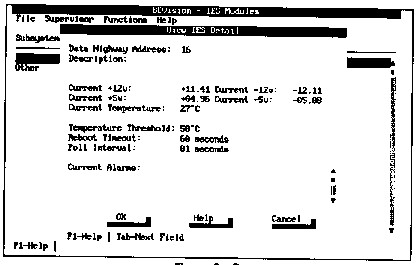 Figure 3-3
The fields displayed include:
IES Communication Failure
Power Supply Failure
Voltage Threshold Exceeded
Fan Failure
Slot Fuse Failure
Temperature Threshold Exceeded
Floppy Fuse Failure
Keyboard Fuse Failure
Group Power Failure
View BC Processors
To monitor and control the BC processors installed in a subsystem, highlight the IES in that same subsystem and select the View BC Processors option from the Functions Menu (or press <Enter>). The BC Status Screen will be displayed. An explanation of this screen and its functions is included in the next section of this chapter.
View SCSI Drives
To monitor and control the SCSI hard drives installed in the SafeStor/FT, highlight the SafeStor/FT subsystem and select the View SCSI Drives option from the Functions Menu (or press <Enter>). The SCSI Drives Status Screen will be displayed. An explanation of this screen and its functions is included at the end of this chapter.
Setup
Use this function to configure each IES. The Setup option must be run on an IES before it will appear on the IES Status Screen. The information which is specified using this option includes:
In addition, when the Setup option is chosen, BCVision determines the validity of the software running on the IES. If no software is running on the IES, or the software is out of date, BCVision will prompt the user to transfer new software to the IES.
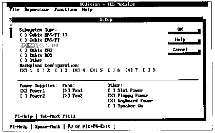
When prompted for the data highway identification number, enter the number (1 to 31) set on the hardware switch of the IES to be configured. If this IES has been configured previously, its current setup will display. Figure 3 - 4 illustrates the IES Setup Screen displayed if the specified IES is integrated into an ERS/FT II subsystem. Figures 3 - 5 through 3 -7 illustrate the setup screen for the ERS/FT II subsystem’s PCI backplane configurations. Figure 3 - 8 illustrates the IES Setup Screen displayed for subsystem types other than the ERS/FT II or the SafeStor/FT. The SafeStor setup screen is illustrated in Figure 3 - 9.
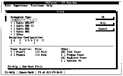
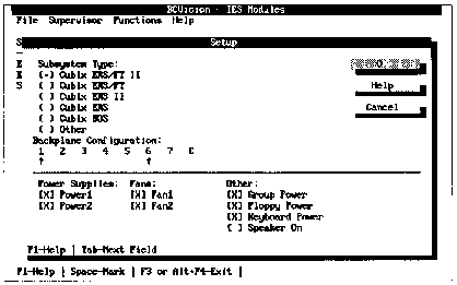 Figure 3-5
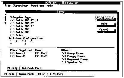
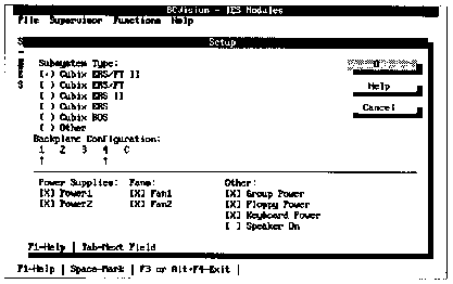
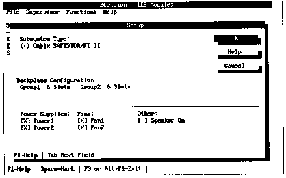
Note! Since BCVision automatically detects ERS/FT II and SafeStor/FT subsystems and sets the subsystem type accordingly, the user cannot manually set the subsystem type.
The first time a subsystem is set up, a default configuration is displayed based upon the subsystem type.
The Backplane Configuration defines the segment definition of the subsystem. In ERS/FT II and SafeStor/FT subsystems, this information is detected automatically and displayed; it cannot be modified via the Setup Screen.
Backplanes in BOS, ERS II, ERS or ERS/FT subsystems must be configured by the user. The ERS II, ERS, and ERS/FT subsystems may contain 1 to 8 groups, or segments. Each group functions as a separate backplane. Since up to eight groups may reside in one subsystem, a multiplexor panel residing in the subsystem contains eight sets of connectors, one for each possible group. Specify which of these connectors are actually attached to a BC processor.
Mark only those positions which correspond to the physical location of the connectors in use. For example, if connectors 1 and 5 are marked under Setup, BCVision will view the subsystem as having two groups (Group 1 and Group 2), and the IES will attempt to communicate with the Group 1 BC processor via mux connector 1 and the Group 2 BC processor via mux connector 5.
The BOS 100 subsystem is different in that it always contains 5 groups regardless of the number of BC processors installed. This is reflected on the group selection display on the front panel of the BOS, which cycles through groups 1 to 5. To properly set up a BOS, mark the first five physical groups in use. This allows the BCVision group representation to match the BOS subsystem's panel display. If a group does not contain a BC processor, the BC Status Screen will display it as "Not Attached".
Specify the number of power supplies that are monitored by the IES. Only Cubix manufactured power supplies may be monitored by the IES. Table 1-1 indicates which subsystems contain supplies that can be monitored. ERS/FT systems may optionally contain two Cubix power supplies. To indicate the number of power supplies to be monitored, select either Power 1 or Power 2, or both. No selection means no power supplies are to be monitored. An alarm is generated if a power supply fails.
Specify the number of fans that are to be monitored by the IES. In ERS II and ERS/FT II subsystems, both fans are monitored. Therefore, this field defaults to two for these subsystem types. In ERS, ERS/FT, and BOS subsystems only lock rotor fans can be monitored. Because lock rotor fans are not always installed, this field defaults to no monitorable fans for these subsystem types. You may select Fan 1, Fan 2, or both to indicate the number of lock rotor fans to be monitored. No selection means no lock rotor fans are to be monitored. An alarm will be generated if a fan fails.
Other miscellaneous information includes the following:
The Setup screen may prompt the user to transfer the IES software to the IES being configured. BCVision transfers the software over the Cubix data highway. An IES is not fully functional until it has been configured by the Setup option and its software has been transferred.
Note! Performing an IES software transfer will clear the reset counters for the BC processors installed in the current IES. For an explanation of reset counters, refer to the View Processor Detail option of the Functions Menu on the BC Status Screen included in the next section of this chapter.
Scan Data Highway
When the BCMaster TSR is loaded, it automatically scans the Cubix data highway for sensors. To be found, an IES must be connected to the highway and be supplied with power. Each IES on the highway must also be configured with a unique identification number using a hardware switch on the IES.
Each IES contains a PROM used for data highway communications. However, most of the software which runs on the IES is transferred to the IES by BCVision from a firmware file (IESFRMWR.BIN). This allows the firmware to be easily updated in the field.
As BCMaster performs its initial scan it displays a message on the screen for each IES found. The revision of the PROM on the IES is included, as is the state of the Firmware and Setup configuration. If the Firmware is invalid or out of date, or the Setup is invalid, the IES needs to be configured using the Setup option. The BCMaster display may optionally be written to a file using standard DOS methods of redirection. Examine the BCMaster information and verify that all sensors are located. If an IES is not listed, verify its connection to the data highway. Also confirm that it is assigned a unique identification number by inspecting its switch setting.
BCVision builds an internal list of all sensors found during the initial scan. BCVision will poll each IES on this list for status and alarm conditions. The Scan Data Highway option on the Functions Menu causes BCVision to rebuild its internal list by performing another data highway scan. Once this function is performed BCVision communicates only with the sensors it finds during the new scan.
If BCVision loses communication with an IES, it generates an alarm and removes the IES from the internal list. BCVision makes no further attempts to communicate with this IES until the IES is functional and another scan is performed.
During a data highway scan BCVision attempts to communicate with each IES. If the IES responds, it is added to the list; otherwise a communication timeout occurs and BCVision proceeds to the next IES. To reduce the amount of time required to scan for sensors which are not present on the highway, BCVision provides a method of specifying the first and last IES identification numbers to be scanned. The scan function will consecutively attempt to communicate with each IES identification number starting with the number specified as the Beginning Highway Address and ending with the Ending Highway Address. The default range is 1 to 31.
Mark All
Selecting this option marks all sensors listed on the IES Status Screen. The Mark All option provides a easy way to perform an option once for all sensors in the IES Supervisory System. Individual sensors may be marked by highlighting the IES on the IES Status Screen and pressing the <Space Bar>.
Help Menu The options on the Help Menu are:In addition, the <F1> function key provides help on the current function.
Press Esc to exit the menu.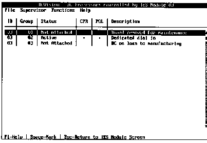
For each BC processor in the subsystem, the BC Status Screen displays the IES identification number, the group number, the status, CPR condition, Pending Offline condition, and description.
The ID refers to the data highway identification of the current IES as determined by a hardware switch setting on the IES. Since the BC processors displayed are in the same subsystem, the ID number is the same for all of them.
The group number identifies which group in the segmented backplane of the subsystem contains the BC processor. Groups are defined for each subsystem as part of the Setup option performed from the Functions Menu of the IES Status Screen.
The current status of each BC processor is displayed as follows:
The CPR field indicates whether the automatic Cubix Processor Recovery function is enabled on this processor.
The POL field indicates whether the Pending Offline function is enabled on this processor.
The Description is specified by the user to describe and identify each BC Series processor.
From the BC Status Screen the following functions are available:
Help
Press <F1> to view help information describing BCVision.
Mark
Some of the options available from the Functions Menu operate on BC Processors that are "marked". To mark a processor, use the arrow keys to position the highlight bar on the BC to be marked, and press the <Space Bar>. Marked processors are indicated by a background color of dark blue. To unmark a BC processor, press the <Space Bar> again, and the color will return to its previous state.
Operations on the Functions Menu may be performed on multiple BC processors simultaneously by marking all of the processors to which the function applies and then executing the function. For example, assume that all of the BC processors are marked and the reset function is selected. All of the processors will be reset.
The ability to Mark All BC processors is available under the Functions Menu. This is a convenient way of performing a single function for all of the processors in a subsystem.
Reset
Pressing <Alt>+R instructs BCVision to reset all of the marked BC processors. If no processors are marked, the reset will be performed on the currently highlighted BC. The reset is generated by the IES in the subsystem with the BC processors. This is a hardware reset, and will reset the BC processors regardless of their state. If Confirmation is enabled (via the Supervisor Menu), a message requesting user verification will be displayed before the processors are actually reset.
Access Menu Options
The menus are accessed from the BC Status Screen the same way they are accessed from the IES Status Screen. The options available from each menu are also the same, with the exception of the Functions Menu.
Functions Menu
The options available from the Functions Menu include:
All of the functions except Mark All will apply to all marked BC processors. Marked processors are indicated by a dark blue background. If no processors are marked, the function will be performed on the currently highlighted BC (the highlight is indicated by a white foreground).
Press Esc to exit the menu.
Reset Processor(s)
Selecting this option causes all marked BC processors to be reset. Note that this function is also available by using the <Alt>+R hot key sequence from the BC Status Screen. Refer to the previous description of the reset function for more information.
Clear Reset Counters
Each IES maintains three counters for each BC Series processor being controlled. They are:
Selecting the Clear Reset Counters option instructs BCVision to initialize all of the counters for the marked BC Series processors to zero. Note that these counters are also cleared when the IES software is transferred to the IES.
Set Processor(s) Online
An offline processor may be placed online by selecting this option. Only marked processors with a status of "Offline" will be affected by execution of this function. Any processor that is displayed on the BC Status Screen that is not indicated as "Offline" is considered to be online, even if its status is "Inactive".
Note! The status of Pending Offline will be set to Disabled by the Set Processor(s) Online option.
Set Processor(s) Offline
Any marked processor on the BC Status Screen may be placed offline and held in an offline state by executing this option from the Processor Menu. To achieve an offline condition, the IES places the processor into a reset state and holds it in this condition until the processor is placed online using the Set Processor(s) Online option. Therefore, processors should not be taken offline while they are currently in use.
Note! To prevent the BC Supervisor from being placed off-line, the keyword "Super" (case insensitive), must be entered in the Description field of the BCVision - IES Modules screen. See Step 16 of the Installation Instructions in Chapter 2.
Enable CPR
Selecting this option from the Functions Menu enables the CPR feature on the marked BC Series processors.
Note! Enabling CPR on BC processors functioning as NetWare file servers is not recommended. File servers should be brought down in an orderly manner by the system administrator. If CPR is enabled on a file server, first verify that the BCACTIVE.NLM control software is properly installed (refer to the BC Series Software Installation Guide).
Disable CPR
Selecting this option from the Functions Menu disables the CPR feature on the marked BC Series processors.
Enable Pending Offline
Selecting this option from the Functions Menu enables the Pending Offline feature on the marked BC processors. If Pending Offline is enabled on a processor, the IES Supervisory System monitors the processor until it is reset. Once the BC is inactive for any reason, the IES holds the processor offline and BCVision generates an alarm stating that the BC has gone offline. This is a useful maintenance feature when used in conjunction with the BC reset on loss of carrier option. By enabling the Pending Offline option on all processors residing in a subsystem which is used for remote communications, an orderly shutdown of that subsystem may be performed. As users disconnect their remote sessions, carrier is lost and the BC processors reset. BCVision notifies the user and holds the processors offline, thus preventing other remote sessions from being initiated on those processors. When all active sessions are terminated in this fashion, the subsystem may be taken offline for maintenance in an orderly manner.
Note! Enable Pending Offline cannot be set for any BC with the keyword "Super" in its Description field.
Note! If Pending Offline is enabled on a BC that transitions between NetWare and DOS, the processor will be taken offline. This occurs because the IES interprets the transition as a reset condition.
Disable Pending Offline
Selecting this option from the Functions Menu disables the Pending Offline feature on the marked BC processors. Refer to the Enable Pending Offline option for an explanation of Pending Offline.
Note! If the BC processor is offline when Pending Offline is disabled, the IES Supervisory System attempts to place the processor Online.
Group Power Off
Applies to the ERS/FT II subsystem only. Group Power Off allows the slot group containing the marked BC processor to be turned off remotely. If multiple BC processors are marked, each group containing a marked BC is powered off.
Note! If the keyword "Super" is in the Description field of the marked BC a warning message notifies you that you are about to power off the BC Supervisor.
Group Power On
Supported by the ERS/FT II subsystem only, this feature allows power to a group of slots containing the marked BC processor to be turned on remotely. It has the same affect as pressing the group power on switch on the console of the ERS/FT II subsystem. If multiple BC processors are marked, each group containing a marked BC will be powered on.
WARNING!
Do NOT turn group power on to a group in a subsystem being serviced! If power is applied to a group while boards are being installed or removed, or slots in the subsystem are being accessed for any other reason, damage may occur to the equipment if power is turned on.
View BC Processor Detail
The user may view detailed information describing each BC processor displayed on the BC Status Screen. The Processor Detail Display may be accessed from the Functions Menu or by using the <Alt>+V hot key sequence. The BC processor for which the Detail Display is generated will always be the BC that is currently highlighted. Figure 3 - 11 provides a sample Processor Detail Display screen.
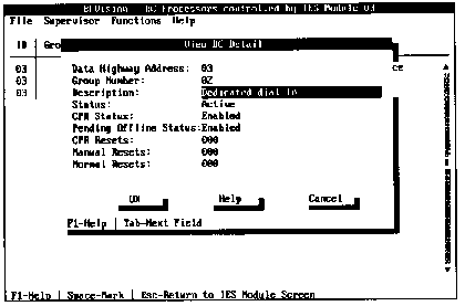
The fields displayed include:
CPR Resets - the number of resets performed automatically by the CPR function.
Manual Resets - the number of resets requested by the user via SNMP or BCVision.
Normal Resets - the number of resets performed on this processor by the user (Ctrl+Alt+Del) or reset on loss of carrier. Reset on loss of carrier is a configurable BC processor option (refer to the appropriate BC Series Hardware Installation Guide).
Note! The Normal Resets counter will be incremented when a BC Series processor transitions between running DOS and running NetWare 3.x/4.x. During this transition, the BC processor is not able to respond to the IES, and therefore the IES detects a processor reset. After the BCACTIVE.NLM is loaded, the BC processor resumes responding to the IES, and the IES detects it as active.
The Reset Counters may be cleared on demand from the Functions Menu. They are also cleared automatically each time new IES software is transferred to the IES.
Mark All
Selecting this option from the Functions Menu marks all BC processors listed on the BC Status Screen. All of the other options available from the Functions Menu apply to "marked" sensors. The Mark All option provides a simple way to perform an option once for all processors in the subsystem with the current IES. Individual processors may be marked by highlighting the processor on the BC Status Screen and pressing the <Space Bar>.
SCSI Drives Status Screen This screen displays status information on all SCSI drives installed in the subsystem of the current IES. To access this screen from the IES Status Screen, highlight the desired IES and press <Enter> (or select the View SCSI Drives from the Functions Menu). A screen similar to the one in Figure 3 - 12 will be displayed.
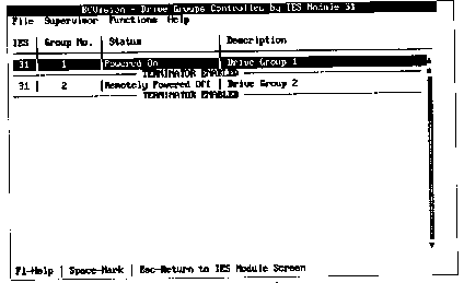
For each SCSI drive in the subsystem, the SCSI Drives Status Screen displays the IES identification number, the slot number, the status, disk utilitzation, and description.
The IES ID refers to the data highway identification for the current IES. This ID is determined by a hardware switch setting on the IES. The ID number is the same for all drives in the same subsystem.
The slot number identifies which group in the segmented backplane of the subsystem contains the SCSI drive adapter. Groups are defined for each subsystem as part of the Setup option performed from the Functions Menu of the IES Status Screen.
The current status of each SCSI drive is displayed as follows:
Online The SCSI drive is online. Power is applied and the drive is operational
Offline The IES is holding the drive offline. The drive is not operational
Installed A SCSI drive is physically attached to this slot
Not Installed No SCSI drive is physically attached to this slot or the drive key has not be turned to the ON position.
The Utilization field indicates the percentage of disk activity. Disk activity is measured at intervals of one second; however, the refresh rate set during configuration determines how frequently the activity updates on the screen.
The Description is specified by the user to describe and identify each SCSI drive.
From the SCSI Drives Status Screen the following functions are available:
Help
Press <F1> to view help information describing BCVision.
Mark
Some of the options available from the Functions Menu operate on SCSI drives that are "marked". To mark a drive, use the arrow keys to position the highlight bar on the drive to be marked, and press the <Space Bar>. Marked drives are indicated by a background color of dark blue. To unmark a drive, press the <Space Bar> again, and the color will return to its previous state.
Operations on the Functions Menu may be performed on multiple SCSI drives simultaneously by marking all of the drives to which the function applies and then executing the function. For example, assume that all of the drives are marked and the "Set SCSI Drives Offline" function is selected. All of the drives will be placed offline.
The ability to Mark All SCSI drives is available under the Functions Menu. This is a convenient way of performing a single function for all of the drives in a subsystem.
Access Menu Options
The menus are accessed from the SCSI Drives Status Screen the same way they are accessed from the IES Status Screen. The options available from each menu are also the same, with the exception of the Functions Menu.
Functions Menu The options available from the Functions Menu include:
All of the functions except Mark All and Modify Descriptions for Drive will apply to all marked drives. Marked drives are indicated by a dark blue background. If no drives are marked, the function will be performed on the currently highlighted drive (the highlight is indicated by a green background).
Press Esc to exit the menu.
Set SCSI Drives Online
An offline drive may be placed online by selecting this option. Only marked drives with a status of "Offline" will be affected by execution of this function.
Set SCSI Drives Offline
Any marked drive on the SCSI Drives Status Screen may be placed offline and held in an offline state by executing this option from the Function Menu. The IES places the drive into an offline state and holds it in this condition until the drive is placed online using the Set SCSI Drives Online option.
Modify Description for Drives
The option may be used to modify any name or description in the Description field of the SCSI Drives Status Screen. If no name or description exists for a specific drive, you may enter up to 31 alphanumeric characters to name or describe the marked drive. To do this, use the arrow-keys to highlight the drive to be named or modified. Select the Modify Description for Drive option from the Functions Menu and press <Enter>. Type the name or description and press <Enter>.
Mark All
Selecting this option from the Functions Menu marks all drives listed on the SCSI Drives Status Screen. All of the other options available from the Functions Menu apply to "marked" SCSI drives. The Mark All option provides a simple way to perform an option once for all SCSI drives in the subsystem with the current IES. Individual drives may be marked by highlighting the it on the SCSI Drives Status Screen and pressing the <Space Bar>.