 |
|
|
|
BC Triton
Series
Chapter 3 - Installation
Hardware Installation
Installation in a Cubix Enclosure
PCI Extension Overview
The BC Triton boards support PCI bus extension via the connection of an optional PCI bus extender card. The extender card, which connects to the 80-pin connector at location J16 on the BC board, extends the PCI bus to an ERS/FT II PCI Master Interconnect Board (MIB). When installed in the ERS/FT II subsystem, the ISA connectors on the BC board and the PCI connectors on the PCI bus extender card simultaneously engage the ISA and PCI connectors on the MIB. The only subsystem that supports PCI extensions is the ERS/FT II.
Two PCI extender cards are available, passive and active.
The passive extender card (figure 3-1) is used on PCI MIBs with one or two PCI expansion slots.
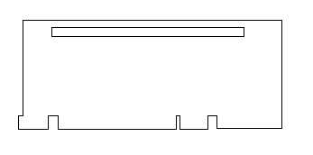
Figure 3-1, Passive PCI Extender Card
The active PCI extender card (figure 3-2) is equipped with a PCI-to-PCI bridge controller that extends the PCI bus to a maximum of four external controllers. The active PCI extender card is designed for use with MIBs having three to four PCI adapter slots for each BC Triton board installed. MIBs having fewer than three PCI adapter slots per BC installed will not support the active PCI extender card. The only MIB supporting the active card is the 2x5 PCI + 2x2 ISA.
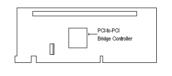
Figure 3-2, Active PCI Extender Card
PCI Bus Extender Card Installation
The PCI bus extender card is shipped with four #6 screws and two spacers. These parts are used to secure the extender card to the BC processor.
SCSI Device Installation
The Symbios SCSI adapter on the BC Triton series supports:
SCSI BIOS Configuration
A SCSI configuration utility is available on boot-up of the BC processor. Shortly after the SCSI BIOS information displays, the configuration program can be accessed by pressing Control C. The configuration utility will allow you to scan the SCSI bus, change configuration options, and view a list of SCSI devices connected to the board.
SCSI Drivers and Utilities
The Symbios Driver diskettes contain various drivers, utilities and installation instructions. The utilities include a SCSI format program, a MSDOS configuration program, and a diagnostics program.
SCSI Termination
On-board SCSI termination is controlled by dip switches 4 and 5 of switch S2. Normally, both switches are off, which terminates the high and low order bits of the SCSI bus.
The following four diagrams show the switch settings for proper SCSI termination with SCSI devices connected to connectors J14 (50 pin) or J18 (68 pin).
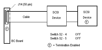
Figure 3-3, 8 Bit External OR Internal SCSI devices

Figure 3-4, 8 Bit Internal AND External SCSI devices

Figure 3-5, 16 Bit Internal OR External SCSI devices
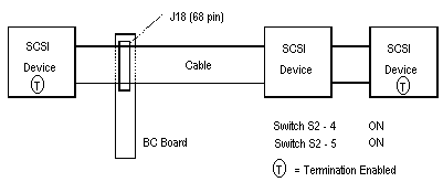
Figure 3-6, 16 Bit Internal AND External SCSI
devices
Note: Termination should also be configured as "enabled" if the SCSI interface is not used. The last device on the SCSI cable must also supply a termination load to the cable. SCSI devices not at the end of the cable must have their termination loads disconnected. Enabling and disabling a SCSI device's termination may involve a switch or shunt setting or the installation or removal of resistive SIP or DIP packages on their circuit board. Consult the installation manual for the SCSI device to determine its termination options.
Optional Video, Keyboard & Mouse
The video, keyboard, and PS/2 style mouse signals are normally cabled from headers on the top of the BC board to a Cubix multiplexer where they are ultimately brought out to standard connectors and attached to a monitor, keyboard, and mouse. If a multiplexer is not used, Cubix can provide an optional adapter. This adapter is a printed circuit board and bracket that provide an interface between the BC headers and the Mini-DIN 6 and HD DSUB-15 connectors needed to connect a VGA monitor and PS/2 style keyboard and mouse. These optional connectors may be installed in an empty slot (where the end bracket of a board would normally be), or in the additional connector space of an auxiliary junction panel.
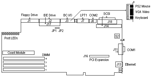
Figure 3-7, BC 5xxx with Video/Keyboard/Mouse
Adapter
WARNING!
WHEN HEADER J3 IS NOT CONNECTED TO THE MULTIPLEXER, THE PROCESSOR WILL NOT SUPPORT THE MULTIPLEXED FLOPPY INTERFACE.
Optional LPT1
An optional parallel port may be added to function as LPT1 on the BC. This requires a Cubix LPT1 printed circuit board adapter and bracket which provide an interface between the BC header (J7) and the DB-25 connector. The optional connector may be installed in an empty slot (where the end bracket of a board would normally be), or in the additional connector space of an auxiliary junction panel.

Figure 3-8, BC 5xxx with Optional LPT1 Adapter
Optional COM2
An optional second serial port may be added to function as COM2 of the BC. Connecting COM2 requires a Cubix printed circuit board adapter and bracket, which provide an interface between the BC header (J8) and the DB-9 connector. The connector may be installed in an empty slot (where the end bracket of a board would normally be), or in the additional connector space of an auxiliary junction panel.
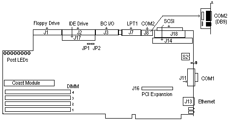
Figure 3-9, BC 5xxx with Optional COM2 Adapter
Peripheral Adapter Installation
Follow the steps below to install optional Cubix adapter boards for peripheral devices such as video, keyboard, mouse, and LPT1.
WARNING!
MAKE SURE THE SYSTEM IS POWERED OFF AND UNPLUGGED BEFORE BEGINNING THIS PROCEDURE.
Software Installation
Overview
To fully utilize all of the features integrated into the BC Series processors, the following software drivers and utilities are available:
BC Series Software
The functions provided by the BC Series Software are:
DEC 21140 PCI Fast Ethernet Drivers
The DEC Ethernet Drivers are required if using the on-board Ethernet controller. The driver diskettes provided by Cubix contain the following drivers and installation instructions.
S3 Trio64V+ (765) Video Drivers
The S3 Drivers may be required by some operating systems or application programs. The driver diskettes provided by Cubix contain the following drivers and installation instructions.
Symbios 825A SCSI Drivers
The Symbios (NCR) Drivers may be required when installing SCSI devices on the BC Series board. The driver diskettes provided by Cubix contain the following drivers and installation instructions .
BC Series Software Installation
DOS Environment
BCSETUP
The Cubix DOS device driver BCSETUP.SYS supports the Cubix Supervisory System by providing an interface between the IES module and a BC processor running DOS. BCSETUP.SYS also provides remote mouse and keyboard support as well as mouse multiplexer support.
A mouse driver (e.g. Logitech's MOUSE.COM or Microsoft's MOUSE.EXE) must be loaded for BCSETUP.SYS to provide mouse support.
To install this driver on disk drives formatted with the DOS operating system, copy the BCSETUP.SYS file from the \DOS directory of the BC Series Installation Diskette to the root directory of the boot drive. Next, add the following line to CONFIG.SYS file in the root directory of the drive:
device = bcsetup.sys
This sets the following defaults:
The following is a list of options that may be used with this command. Place them on same line in the CONFIG.SYS file.
Command line options are not case sensitive.
| Command Line Option | Explanation |
| -n | 83/84 key keyboard |
| -m | disable mouse support |
| -i=x or -int=x | hook interrupt x (decimal) for the Cubix supervisor interface, where x= 10, 15 or "no". The "i=no" option disables the supervisor interface support in BCSETUP and frees interrupts 10 and 15. |
| -ep | enables BC processors equipped with a BC
NET UART (e.g., BC Triton), to be monitored by an IES I (original) module when installed
in an ERS II subsystem. To determine if an IES I module is installed in the ERS II
subsystem, refer to the following section "How to Differentiate an IES I from and IES
II Module." Do not use the -ep command if an IES II (enhanced) module is installed in the ERS II subsystem. |
Table 3-1, BCSETUP Command Line Options
Command Line Examples
For example, to load BCSETUP for an 83/84 key keyboard, without mouse emulation, and hooking interrupt 10 for the supervisor interface support, the command line in the CONFIG.SYS file would appear as follows:
device = bcsetup.sys -n -m -i = 10
All BC mouse software is designed to be used explicitly with Logitech PS/2 style mice. If non-Logitech mice are to be used, the command line option -nl should be entered in the config.sys file following the mouse emulation software filename:
device= bcsetup.sys -nl
The -nl option disables the synchronizing algorithms specific to Logitech mice. As a result, mouse multiplexing is not supported.
Finally, reboot the BC processor to allow the modifications in the CONFIG.SYS file to take effect.
How to Differentiate an IES I Module from an IES II Module
To determine if an IES I module is installed in the ERS II subsystem, remove the subsystem's cover and locate the IES module. Either a 26-pin ribbon connector or a 3-pin molex connector will be located at the top of the board next to the "L" bracket. If the connector is a 26-pin ribbon connector, the module is an IES I. If a 3-pin molex connector is at this location, the module is an IES II.
Windows 3.1x Environment Installation
VHOTFIX
The Cubix virtual device driver VHOTFIX.386 will "hot fix" a mouse in the Windows environment, allowing a mouse to function properly if it is attached locally to the BC processor after Windows is invoked, or if it is attached through a Cubix multiplexer and multiplexed to the BC processor after Windows is invoked.
To install this virtual device driver with Windows, first install BCSETUP as described in the DOS Environment Installation section. Locate the directory containing Windows virtual device driver files. They may be identified by their .386 extensions and are usually located in the \WINDOWS\SYSTEM directory. Copy the file VHOTFIX.386 from the \DOS directory of the BC Series Installation Diskette to the directory containing the other virtual device drivers. Modify the [386enh] section of the Windows SYSTEM.INI file (usually in the \WINDOWS directory) to include the line:
device = vhotfix.386
This program will function only if the device driver BCSETUP.SYS v1.10 or above is loaded in the CONFIG.SYS. Finally, reboot the BC processor to allow the modifications to take effect.
Windows NT Drivers
Beginning with version 2.17, the BC Series Installation Diskette includes an InstallShield setup program to install these NT files:
Installation
BCACTVNT
The Cubix device driver BCACTVNT.SYS supports the Cubix Supervisory System by providing an interface between the IES module and a BC processor running Windows NT.
CBXI8042
CBXI8042.SYS is a complete multiplexed mouse and keyboard device driver for BC Series processors running Windows NT. CBXI8042.SYS replaces the I8042PRT.SYS device driver file provided with Windows NT.
To install either BCACTVNT.SYS or CBXI8042.SYS, run the InstallShield setup program found in the \WINNT subdirectory of the BC Series Installation Diskette.
To run Setup from the DOS command prompt, type
a:\winnt\setup
Setup provides the option of installing either BCACTVNT.SYS or CBXI8042.SYS. Follow the prompts provided by the Setup program to install either of these drivers.
OS/2 Environment Installation
BCSETOS2
The Cubix device driver BCSETOS2.SYS supports the Cubix Supervisory System by providing an interface between the IES module and a BC processor running OS/2.
To install this driver, copy the file BCSETOS2.SYS from the \OS2 directory of the BC Series Installation Diskette to the root directory of the boot drive. Next, add the following line to CONFIG.SYS file in the root directory of the boot drive:
device = bcsetos2.sys
This will give the default option of interrupt 15 (decimal) for the Supervisor interface. If interrupt 10 is preferred, it must be specified on the same line in the CONFIG.SYS file. To load BCSETOS2 to use interrupt 10, the line in the CONFIG.SYS should appear as follows:
device= bcsetos2.sys -i = 10
If BCSETOS2.SYS is not specified in the CONFIG.SYS file, the BC will not support the Cubix Supervisory System and interrupts 10 and 15 are available for other uses. Finally, reboot the BC processor to allow the modifications to take effect.
CBXMOUSE
The Cubix device driver CBXMOUSE.SYS provides mouse emulation and mouse multiplexer support for BC Series processors running OS/2 operating system.
To install this driver, copy the file CBXMOUSE.SYS from the \OS2 directory of the BC Series Installation Diskette to the \OS2 directory of the boot drive. Next, modify the CONFIG.SYS file in the root directory of the boot drive as follows:
remark out the line:
device = os2\mouse.sys
by placing "REM" in front of it, so that it reads:
rem device= os2\mouse.sys
add the line:
device = os2\cbxmouse.sys
CBXMOUSE.SYS is a fully functional mouse driver that replaces the MOUSE.SYS driver. CBXMOUSE.SYS loads PS/2 mouse support whether or not a mouse is physically present.
All BC mouse software is designed to be used explicitly with Logitech PS/2 style mice. If non-Logitech mice are to be used then the command line option -nl should be entered in the config.sys file following the mouse emulation software filename:
device= cbxmouse -nl
The -nl option disables the synchronizing algorithms specific to Logitech mice. As a result, mouse multiplexing is not supported.
Finally, reboot the BC processor to allow the modification in the CONFIG.SYS to take effect.
CBXMOUSE is intended for use in systems equipped with the Cubix multiplexer. If a mouse is to be shared by multiple OS/2-based processors via the multiplexer, the mouse must be booted on an OS/2 system (i.e. an OS/2-based processor must be selected by the multiplexer when the system is booted)
Windows 95 PS/2 Mouse Driver
This driver provides PS/2 mouse support on processors running Windows 95. If a Cubix mouse driver for Windows 95 was previously installed on a BC processor, the old files must be deleted before installing the new PS/2 mouse driver.
To Remove Old Cubix Windows 95 Mouse Driver Files:
To Install the Cubix PS/2 Mouse Driver for Windows 95:
Operating the Mouse after Installation
To ensure the mouse functions properly during normal operations, be sure to "power on" the system and initiate resets as described below:
Note: Avoid moving the mouse when selecting channels and do not switch channels while the processor reboots.
Resetting a Processor
Before initiating a "reset," make sure the mouse is attached and its channel selected on the subsystem's front panel. Also, make sure the processor loads into Windows 95. When the Windows 95 screen appears, the mouse should be functional. If the mouse does not work, disconnect then reconnect the mouse connector.
When Powering Up the Subsystem:
When the subsystem is powered up, make sure at least one processor completes the boot process with the mouse attached and its channel selected. If the mouse does not work, disconnect then reconnect the mouse.
NetWare Environment Installation
BCACTIVE
BCACTIVE.NLM is a NetWare Loadable Module (NLM) that supports the Cubix Supervisory System by providing an interface between the IES module and a BC processor running NetWare 3.x/4.x. To install Cubix Supervisory support on a BC processor running NetWare, first install the BCSETUP.SYS device driver on the DOS partition as previously explained in the DOS Environment Installation section. Then install the BCACTIVE.NLM on the NetWare partition. Both BCSETUP.SYS and BCACTIVE.NLM must be installed with the same interrupt configuration.
To install the NLM on a BC processor functioning as a NetWare 3.X/4.x server, copy the file BCACTIVE.NLM from the NetWare subdirectory of the BC Series Installation Diskette to the SYSTEM subdirectory of the SYS volume of the NetWare server. Next, add the following line to the AUTOEXEC.NCF file on the NetWare partition:
load bcactive 15
This will load BCACTIVE.NLM with the default IRQ 15 configuration. Two interrupt levels are supported by the BC hardware: IRQ 10 and IRQ 15. If the IRQ 10 configuration is preferred, modify the load command as follows:
load bcactive 10
BCACTIVE must have a command line parameter specifying the IRQ and this must match the IRQ configuration of BCSETUP. BCACTIVE should not be loaded if BCSETUP is loaded without BC Supervisory System support (bcsetup.sys -INT= NO)
Acquiring Additional or Updated Drivers
BC Series Software, DEC Ethernet, Symbios, and S3 Drivers are available on the Cubix Customer Support BBS at (702) 888-1003 (No parity, 8 data bits, 1 stop bit)
This document, and all Web contents, Copyright © 1997 by Cubix Corp., Carson City, NV, USA.