Installing The DMI Component Interface
Table of Contents
Installing The DMI Component Interface (CI)
The DMI brings manageability and intelligence to computer systems such as desktop PCs and servers, allowing vendors to easily add manageability to their products. The DMI works synergistically with existing standards such as Plug 'n' Play and Simple Network Management Protocol (SNMP). Specifically, AMD's DMI support (MIF file and Instrumentation) extends to the following drivers:
  NDIS 2 DOS driver
  NDIS 2 OS/2 driver
  NDIS 3 Windows for Workgroups driver
  ODI DOS client driver
  ODI OS/2 client driver
The DMI is a local interface to be used within a single system. It provides a means by which component instrumentation developed by multiple vendors can interplay within a single system to uniformly provide management information. The Desktop Management Task Force's (DMTF) DMI interface consists of the following elements:
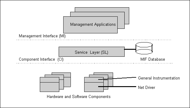
The DMI structure is shown in Figure 9 below.
The Service Layer (SL) is the system-resident program that manages all DMI activities. It is a background task or process that is always ready for a request from a management application or managed components. There are specific implementations of the Service Layer for different operating systems and environments. Refer to the DMI Specification for installation procedures.
The CI, an integral part of the SL, handles communication between component instrumentation and the SL. It shields vendors from the complexity of management information encoding and minimizes the responsibilities of the instrumentation.

Figure 9. Desktop Management Interface Structure
The DMI Installation program edits the PCNET.MIF file and copies the DMI instrumentation files and the MIF file as follows:
| PCNET.MIF | C:\DMI\DOS\MIFS\BACKUP |
| PCNET.OVL | C:\DMI\DOS\BIN |
| PCNET.EXE | C:\DMI\WIN16\BIN |
The installation program performs the following edits to the PCNET.MIF file:
These edits can be done manually if desired. A properly edited
MIF file can be installed with any DMI management application that supports a MIF install feature such as the browser provided with the DMI SDK.
To invoke the AMD DMI installation utility from the distribution diskettes, insert diskette 6 into the A: drive. Issue the following commands (assuming the diskette has the write-protect feature disabled):
  A:>CD \DMI
  A:\DMI>DMINSTL
The installation program can be copied to a directory on the target system and executed from there. The only limitation is that the files to be installed reside in the same directory as the installation program proper (this is true for installation from the floppy drive as well).
Note: When performing the DMI installation using the AMD DMI Installation Utility (DMINSTL), remove all TSRs that are not essential to the installation. For example, if installing on an MS-DOS V6.2 system, pressing the F5 key while the message, "Starting MS-DOS..." is displayed will bypass the system startup files and boot a "clean"
system startup. If using an earlier version of DOS (e.g., V3.3), booting from a floppy without the CONFIG.SYS and AUTOEXEC.BAT file will achieve the same result. Once the system has been started using this method, the DMI installation program can be used to install DMI support for the PCnet drivers.
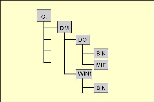
DMINSTL expects the following directory structure to exist in the target environment.
If the directory structure does not exist, the installation
program will create it. See Figure 10.

Figure 10. Directory Structure
DMINSTL interacts with the service layer in one of two ways. If the SL is loaded, the installation program invokes it as required to perform the installation. If the SL is not loaded, DMINSTL loads it before continuing. Once the installation completes, the SL is unloaded if DMINSTL loaded it. If the SL is not available on the target system, DMINSTL copies the PCNET.MIF file both to the C:\DMI\DOS\MIFS and C:\DMI\DOS\MIFS\BACKUP directories.
Once the installation program has been invoked, it presents a forms based interface with two text input fields and two pull down menu fields. To move between the fields, the TAB key is pressed repeatedly until the cursor enters the desired text input field, or until the desired pull down menu field is highlighted.
When the cursor enters a text input field, three actions can be effected on the field itself. The cursor can be advanced one character position for each press of the right-arrow key except at the rightmost position of the field where the cursor ceases to advance. By pressing the left-arrow key, the cursor can be moved to the left by one character position in the same manner as when moving it to the right. Finally, characters entered into the field are placed at the current cursor position and the cursor is advanced by one position to the right. Again, at the
end of the field, the character is inserted but the cursor is not advanced.
When the cursor is placed in a pull down menu field, the field is highlighted. To display the pull down list, press the down-arrow key while holding down the ALT key. Once displayed, the items in the list can be highlighted by using the up and down arrow keys. Pressing the Enter key selects the highlighted item and hides the pull down list. To hide the pull down list without making a selection, press the ESC key.
The F10 key is used to instruct DMINSTL to begin the actual installation process. After filling all the fields as desired, press F10. See the subparagraphs below to get a description of the fields.
DMINSTL will display a progress dialog in the center of the screen. The dialog will alternately draw and erase a blue bar in the center of the screen to demonstrate that the installation is progressing. Once the installation completes, one of two actions will occur. If the installation succeeded, a dialog box appears indicating the success of the operation and the Component ID assigned to the driver. If the installation fails, a message box appears indicating the source of the failure. Again, a key must be pressed to clear the message.
The Serial Number field is used to enter the serial number of the network adapter card package. The number can usually be found on the outside of the package or on the distribution media. The purpose of this field is to allow the serial number of the package to be readily retrieved in case it is required for any purpose such as technical assistance. The Serial Number field is a straight text field. This means that it will accept any text (letters or numbers) that is typed into it.
The Installation Date field is initialized to the system date and time. The field uses the following format.
mmm dd HH:MM:SS yyyy
The 'mmm' portion represents the month. The following values are accepted:
  Jan Apr Jul Oct
  Feb May Aug Nov
  Mar Jun Sep Dec
The 'dd' subfield represents the day of the month and can be any legal value between 1 and 31.
The HH:MM:SS subfield is used to denote the current time. The H, M, and S symbols represent the hours, minutes, and seconds, respectively.
Finally, the 'yyyy' field represents the year.
Any errors detected in the format of the time and date field will cause the value to be rejected and an error message displaying the required format to be displayed.
The Connector Type field identifies the three possible connectors that can be used with the network interface controller. The three connector types currently supported are as follows:
  AUI
  10BaseT (RJ45)
  10Base2 (BNC)
The Connector Type field is a pull down menu field. To display the choices, press ALT-DownArrow.
The Target Driver field identifies the driver to be used with the DMI software. To select the desired driver, pull down (ALT-DownArrow) the menu and select either:
  NDIS 3
  NDIS 2/ODI
The first selection is for use with Windows for Workgroups V3.11. The second is for use with any network operating system that uses either the NDIS 2 or ODI drivers (e.g. LAN Server or Netware, respectively).
The installation program can be terminated at any time prior to pressing F10 to begin the actual installation process. To exit the program, press the F4 key while holding down the ALT key. Once the F10 key is pressed, the installation process must continue until complete.