Density System
Chapter 4 - Maintenance and Repair
Firmware Initialization
The Density Series Intelligent Multiplexor board
comes from the factory preinitialized. Indications of a firmware problem include erratic
front console control and LED display behavior. Contact Cubix Customer Service in the
event of possible firmware-related problems.
Power Supply Replacement
Density Series uses sealed modular power
supplies. Perform the following steps to replace a power supply:
NOTE!
The Density Series system requires two power supplies to provide power
to server
groups. Do not remove more than one power supply from the chassis without
first shutting off power to all groups
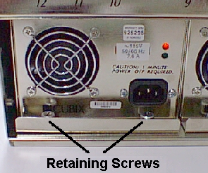
Figure 4-1, Power Supply Retaining Screws
Disconnect the power cord from the power supply.
- Loosen the two retaining screws that secure the power supply to the chassis (figure
4-1).
- Grasp the power supply handle and pull the power supply out of the chassis.
- Insert the replacement supply.
- Secure the retaining screws.
- Connect the power cord.
Fan
Replacement
Remove the front cover of the Density System.
Remove the TOP 2 screws from the fan to be replaced (figure 4-2).
Tilt the top of the fan forward, and carefully remove the fan from the fan housing.
Disconnect the fan power cable from the fan power connector on the system backplane
(figure 4-3).
Reverse the above steps to install the replacement fan.
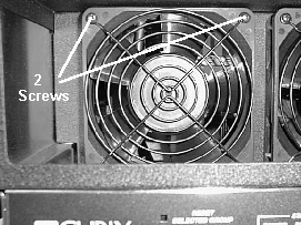
Figure 4-2, Location of Mounting Screws
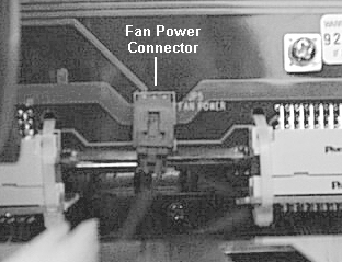
Figure 4-3, Fan Power Connector
Floppy Drive Replacement
Remove the top front cover of the chassis by
loosening the two rear screws and removing the two front screws (figure 4-4).
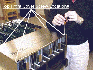
Figure 4-4, Top Front Cover Removal
- Remove two screws securing the floppy disk drive assembly plate to the disk drive bay
(figure 4-5).
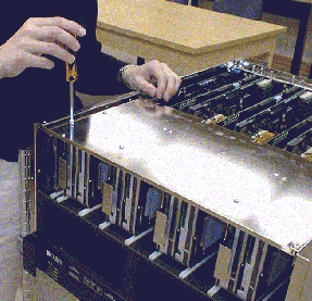
Figure 4-5, Removal of floppy drive assembly securing screws
- Slide the floppy drive out of the hard drive chassis enough to expose the rear
connectors (figure 4-6).
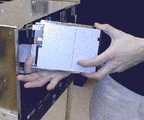
Figure 4-6, Removal of Floppy Disk Drive Cables
Disconnect the floppy ribbon and power cables from
the rear of the floppy drive assembly.
Remove the four screws securing the floppy drive to the mounting assembly.
Reverse the steps above to install the replacement drive.
CD-ROM Drive Replacement
Remove the front cover of the system.
Remove the four front panel mounting screws (figure 4-7).
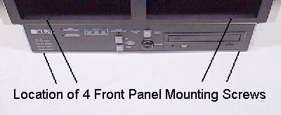
Figure 4-7, Front Panel Mounting Screws
Carefully slide out the front panel.
Remove the four recessed mounting screws for the CD-ROM drive on the bottom of the
system (figure 4-8).
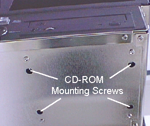
Figure 4-8, CD-ROM Recessed Mounting Screws
Remove the CD-ROM drive.
Disconnect the Data and Power cable.
Reverse the above steps to install the replacement drive.
This document, and all Web contents,
Copyright © 2000 by Cubix Corp., Carson City, NV, USA.
