 |
|
|
|
Density System
Chapter 2 - Installation
Unpacking the System
Installation in a Cubix 1010 Cabinet
WARNING!
Installation of Density Series systems requires two persons. A fully extended system may cause the cabinet to tip over. Do not fully extend a system without first securing the cabinet to the floor. The Density Series system is a rack-mount enclosure designed to be installed in a Cubix System 1010 cabinet or other RETMA-compatible 19" wide equipment rack. Up to two Density Series systems may be installed in a Cubix 1010 cabinet.Multiplexor/IES Switches and Cabling
The Multiplexor/IES board is installed in the leftmost backplane slot as you face the front of the Density System. The switches can be accessed by removing the top cover of the system. Figure 2-1 shows the layout of the Multiplexor/IES board.
Figure 2-1, Multiplexor/IES board Layout
VKM (Video, Keyboard and Mouse) Cabling
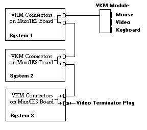
Figure 2-2, Connecting the VKM Module & Cables
These devices may be shared between multiple systems residing in a single cabinet. This is accomplished by daisy-chaining the systems together using the VKM connectors (see figure 2-1 for board layout) on the Mux/IES board.Daisy-chain the systems together using the Cubix supplied DB-25 male-to-male cables as shown in figure 2-2.
Connect the video terminator plug to the unused VKM connectors on the last system.
Connect the unused VKM connector on the first system to the Video/Keyboard/Mouse Breakout Module mounted in the top of the System 1010 cabinet.
If the monitor, keyboard, and mouse are not already connected to the breakout module, route the cables for these devices into the cabinet via the access hole in the top cover and connect the cables to the breakout module.
Key Lock Option Switch (S1)
Key Lock options determine the behavior of the Density system when the console is locked. The options are set with switch 1 on the Multiplexor/IES board (see figure 2-1 for the switch location). Table 2-1, Key Lock Switch DefinitionsOption |
1 |
2 |
3 |
4 |
| Video Only -If this option
is enabled and the console is locked, all of the muxed devices except for the monitor are
disabled. The monitor remains functional on the channel that was selected at the time the
lock occurred. This is a useful feature if there is a management application running on one of the computers in the system. By selecting the processor group containing this computer before locking the console, the screen on the management application can be monitored. However, the other muxed devices and the console functions remain disabled, thus eliminating the possibility of unauthorized intervention. |
on | off | off | off |
| Monitor/Keyboard/Mouse/Reset
-If this option is enabled and the console is locked, the only muxed device that will be
disabled is the floppy disk drive. The monitor, keyboard, and mouse will continue to
function on the selected channel. In addition, the "Reset Selected Group" pushbutton on the front panel of the system will remain functional, allowing an operator to reset the computer selected as the current BC group at the time the console is locked. The "Group Select" pushbuttons are disabled, thus preventing the operator from resetting another processor group. This is a useful feature if the system administrator wants to prevent use of the floppy drive for security purposes. |
Off | On | Off | Off |
| Floppy Channel 1 - If this
option is enabled and either the console is locked or the system is disabled, the floppy
drive will be connected to the first mux channel, regardless of the processor group
currently selected. * This option requires the processor in group one to be connected to the first channel on the Intelligent Multiplexor. If this option is enabled and the floppy fails to function as expected, verify the connection. |
Off | Off | On | Off |
| Master Console Key lock -
Systems may be connected by daisy-chaining them via the VKM connectors on the rear panel
of the Multiplexor/IES board. This connection is required to share a monitor, keyboard,
and mouse between as many as eight systems. If the Master Console Key lock option is enabled, the system will function as a "master console." If the master console is locked, the consoles of all systems connected to the master console are locked, regardless of the position of the key switch on their front panels. A Density Series system will not function as a master console if the system is turned off. A Density Series system with the master console key lock option enabled will remain the Master Console through a power failure. More than one system in a daisy-chain can have the master console key lock option enabled. If this is the case, it is necessary to unlock the key switch on the front panel of each system with the option enabled. As long as the key switch remains in the locked position on any system with the master key lock option enabled, all of the systems in the daisy-chain will remain locked. |
Off | Off | Off | On |
No Key lock Options Enabled - The option switches override one or more of the effects of locking the console using the console key lock. The console key lock is explained in the Console section of this manual. If none of the key lock options are enabled, locking the console disables the following functions:
Muxed device connection (monitor, keyboard, mouse, and floppy drive are disabled) . |
Off | Off | Off | Off |
Integrating Density Series into a
GlobalVision Management System
IES Data Highway Address
The Density Series system includes an out-of-band Data Highway which connects the chassis Intelligent Environmental Sensor (IES) to a GlobalVision management processor (refer to the GlobalVision Management System User’s Guide). This data highway can be daisy-chained between systems to allow management of up to 31 systems from a single GlobalVision management processor.Each chassis connected to the IES data highway must be assigned a unique data highway address. The GlobalVision Console application uses this address to identify and communicate with each IES module. Valid IES addresses range from 1 to 31. The default address of the IES is configured to 1 by Cubix manufacturing.
The Density Series IES is integrated onto the Multiplexor/IES board. The address of this IES is determined by an eight position DIP switch (S3) located on the top edge of the board (see figure 2-1 for switch location).
Table 2-2 contains valid IES switch configurations.
Table 2-2 IES Address Switch Configuration
DIP Switch Position |
||||||||
Address |
1 |
2 |
3 |
4 |
5 |
6 |
7 |
8 |
1 |
OFF |
ON |
ON |
ON |
ON |
ON |
ON |
ON |
2 |
ON |
OFF |
ON |
ON |
ON |
ON |
ON |
ON |
3 |
OFF |
OFF |
ON |
ON |
ON |
ON |
ON |
ON |
4 |
ON |
ON |
OFF |
ON |
ON |
ON |
ON |
ON |
5 |
OFF |
ON |
OFF |
ON |
ON |
ON |
ON |
ON |
6 |
ON |
OFF |
OFF |
ON |
ON |
ON |
ON |
ON |
7 |
OFF |
OFF |
OFF |
ON |
ON |
ON |
ON |
ON |
8 |
ON |
ON |
ON |
OFF |
ON |
ON |
ON |
ON |
9 |
OFF |
ON |
ON |
OFF |
ON |
ON |
ON |
ON |
10 |
ON |
OFF |
ON |
OFF |
ON |
ON |
ON |
ON |
11 |
OFF |
OFF |
ON |
OFF |
ON |
ON |
ON |
ON |
12 |
ON |
ON |
OFF |
OFF |
ON |
ON |
ON |
ON |
13 |
OFF |
ON |
OFF |
OFF |
ON |
ON |
ON |
ON |
14 |
ON |
OFF |
OFF |
OFF |
ON |
ON |
ON |
ON |
15 |
OFF |
OFF |
OFF |
OFF |
ON |
ON |
ON |
ON |
16 |
ON |
ON |
ON |
ON |
OFF |
ON |
ON |
ON |
17 |
OFF |
ON |
ON |
ON |
OFF |
ON |
ON |
ON |
18 |
ON |
OFF |
ON |
ON |
OFF |
ON |
ON |
ON |
19 |
OFF |
OFF |
ON |
ON |
OFF |
ON |
ON |
ON |
20 |
ON |
ON |
OFF |
ON |
OFF |
ON |
ON |
ON |
21 |
OFF |
ON |
OFF |
ON |
OFF |
ON |
ON |
ON |
22 |
ON |
OFF |
OFF |
ON |
OFF |
ON |
ON |
ON |
23 |
OFF |
OFF |
OFF |
ON |
OFF |
ON |
ON |
ON |
24 |
ON |
ON |
ON |
OFF |
OFF |
ON |
ON |
ON |
25 |
OFF |
ON |
ON |
OFF |
OFF |
ON |
ON |
ON |
26 |
ON |
OFF |
ON |
OFF |
OFF |
ON |
ON |
ON |
27 |
OFF |
OFF |
ON |
OFF |
OFF |
ON |
ON |
ON |
28 |
ON |
ON |
OFF |
OFF |
OFF |
ON |
ON |
ON |
29 |
OFF |
ON |
OFF |
OFF |
OFF |
ON |
ON |
ON |
30 |
ON |
OFF |
OFF |
OFF |
OFF |
ON |
ON |
ON |
31 |
OFF |
OFF |
OFF |
OFF |
OFF |
ON |
ON |
ON |
IES Data Highway Cable
After setting the IES address, connect the Density Series system to the Cubix data highway.NOTE !
While similar to an RJ-11 telephone station cable, the data highway
cable is wired as a "straight through" cable and cannot be replaced
using a standard telephone cable. The cable will have a white sticker
marked "Cubix IES Module Only".
* Switch 2 under the IES connectors is not used.
Server Board (DP or SP Series) Installation
The following instructions provide general installation instructions for Density Series compatible server boards. Refer to the appropriate manual with the processor board for configuration instructions.CAUTION!
Group power must be off before installing any Cubix processors or
peripheral boards, or third-party peripheral cards. Failure to follow this
warning may result in damage to the Density Series system and boards
being installed.
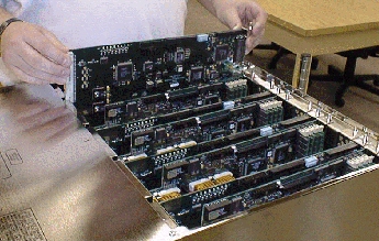
Figure 2-4 Inserting server board in to chassis group slot
Data Highway Adapter
Density Series servers may optionally be used as the GlobalVision Console for a group of Cubix enclosures. The server which will act as the GlobalVision Console requires installation of a data highway adapter on the COM2 port. This adapter provides an interface point for the GlobalVision console processor to collect IES data from all chassis in the data highway chain.Perform the following instructions to install a data highway adapter on a Density Series server.
This document, and all Web contents, Copyright © 2000 by Cubix Corp., Carson City, NV, USA.