BC 4035
Chapter 5 - Troubleshooting
Continual Resets
The Cubix Supervisory System supports a CPR (Cubix Processor Recovery) function designed to automatically reset an inactive BC processor. If a Supervisory System is installed with the CPR function enabled and a BC processor continuously resets, follow the steps below.
QL Boot Problems
QL processors are slave boards that will function as NetWare workstations when they are installed in the backplane of a NetWare file server or MultiProtocol Router (MPR). If a BC processor is configured as this server or MPR, and the QL processors do not boot, attach the video/keyboard adapter board supplied with the QL to the QL processor board and use a monitor to view the boot process of the QL. If the message "Cannot connect to server" is displayed on the QL monitor, run QLVision and view the status of the QL node. If this status shows as Active, attempt to connect to the QL from QLVision. If this connect attempt fails, there is probably an interrupt conflict.
The BC processors use IRQ 15 as the default interrupt for the Cubix Supervisory System. The QL use IRQ 15 as the default interrupt to the NetWare file server or MPR. To correct this conflict, configure the QL driver to use IRQ 11 (0B hexadecimal) or configure the BC to use IRQ 10 (0A hexidecimal).
NIC Driver Installation
To use the integrated Ethernet controller on the BC processor, a NIC driver must be installed. In Novell environments, the name of the driver is PCNTNW.LAN (for BC processors installed as NetWare servers or routers) or PCNTNW.COM (for BC processors installed as NetWare workstations). Complete instructions for NIC driver installations in NetWare and other network environments may be found in the appendices of this manual.
Resets on Modem Initialization
If a BC processor is configured as a host for remote communication sessions, and the BC resets when the remote communication software is loaded, examine switch Sl. If reset on loss of DCD is enabled, the modem is probably toggling DCD during initialization. Contact the modem vendor to determine how to correct this condition.
Remote Boot Problems
The integrated Ethernet controller on the BC 4035 processors supports the ability to remote boot from a NetWare file server. Instructions for enabling this option may be found in Appendix B - Novell ODI Driver Installation. If the remote boot option is enabled, and the BC processor cannot find the file server from which it is to boot, examine the NET.CFG file. Verify that the Frame and Protocol statements have been modified for the 802.2 frame type as follows:
Frame Ethernet 802.2
Protocol IPX EO Ethernet-802.2
Note that the Protocol ID must be changed from 0 (for 802.3) to EO (for 802.2) frame types.
Monochrome Monitor with CubixConnect
Cubix offers a CubixConnect product consisting of Novell's Connect software integrated onto Cubix hardware. Cubix provides software to simplify the installation of CubixConnect in the field. This software can exhibit display problems when run on a BC processor connected to a monochrome monitor.
To correct these video difficulties" use the Cirrus CLMODE utility available on the Cubix BBS (refer to the Acquiring Additional VGA Drivers section of Chapter 3). The command:
forces monochrome graphics support. Using this command will allow the CubixConnect utility to function properly.
Monochrome Monitor on BC Workstation
The default CONFIG.SYS file provided with BC processors includes the following line:
This statement instructs emm386 to include the memory bOO00-bffff in its memory allocations. This can cause a video conflict with monochrome monitors attached to BC processors functioning as NetWare workstations. To resolve the conflict, delete this inclusion and reboot the BC processor.
Mouse Problems
Sometimes problems occur if a mouse is connected to a BC processor via a multiplexor (mux). For proper muxed mouse operation under DOS (or Windows) the following steps must be taken.
If muxed operation is required with Windows, these additional steps must be followed:
Line Busy
If the Line Busy Circuit does not cause the line to appear busy, check the cable connections.
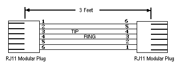
The center two pins of the RJ-11, tip and ring, should measure approximately 48 volts DC under on-hook conditions. When the Line Busy Module has asserted an off-hook condition, the tip-ring voltage should be approximately 8 volts DC.

Figure 5 - 1
RJ-11 Tip and Ring Lines
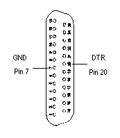
If the Line Busy Circuit is not asserting off-hook, check the state of the DTR signal (pin 4 of the DB-9 RS-232 connector). DTR is false when it is -6 volts with respect to pin 7 of this connector. DTR is true when it is +6 volts with respect to pin 7. The voltage on pin 20 can be measured on the modem DB-25 connector while the computer DB-9 connector is cabled to the Cubix processor.

Figure 5 - 2
DB-25 Connector
If DTR is not changing as expected, check the Cubix processor's COM1 port hardware. Verify the COM1 port configuration in the communication application software.
If DTR is changing properly and the telephone line is not changing from 48 volts to 8 volts, the Line Busy Circuit is probably defective. Contact Cubix Customer Service for assistance.
This document, and all Web contents, Copyright © 1997 by Cubix Corp., Carson City, NV, USA.