 |
|
|
|
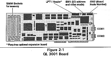
QL 3001
Chapter 2 - Configuration & Installation
Configuration & Installation
Memory
Board Node Number
I/O Address
Video Mode
Math Coprocessor
Installation
* *
This chapter explains how to configure and install a QL 3001 board. Unless otherwise specified, "QL 3001" refers to both the standard QL 3001 and the QL 3001CX. The "QL 3000 Series" includes the QL 3001 and the QL 3002 products.
The QL 3001 configurable options are:
	*	Memory
	*	Board Node Number (Default 1)
	*	I/O Address (Default 220 Hex)
	*	Video Mode
	*	Math Coprocessor
The boards also require an interrupt on the file server or bridge in which they are installed, and also a 16K shared memory window. Both the interrupt and the memory window are shared by all QL 3000 Series boards installed in the server or bridge. These options are software configurable, and are described in the QL 3000 Series Guide to Operations.
The QL 3001 is equipped with a minimum of 2 MB of RAM.
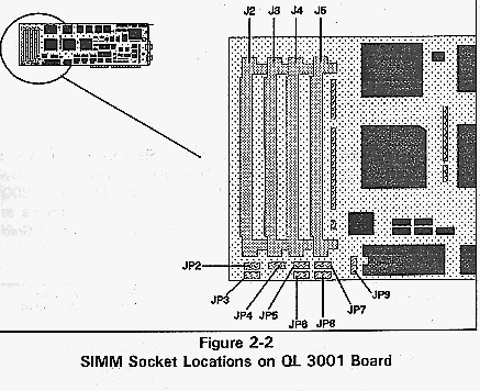
The QL 3001 board's RAM resides in 30pin SIMMs. To add memory, install standard SIMMs or Cubix SIMMs in sockets J2 through J5, and set jumpers JP2 through JP8 to match the memory configuration. Figure 2-2 shows the SIMM sockets and jumpers.
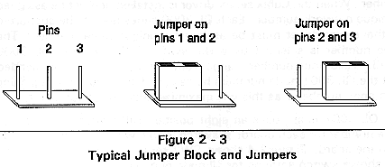
Figure 2-3 shows jumpers and pins on a jumper block. (Jumper JP9 is a manufacturing test jumper. A jumper should be on pins 12 of JP9 for normal operation.)
Table 21 shows the SIMM to install in each socket, and the jumper settings for each memory configuration.
        	            Table 2 - 1
	SIMMs and Jumper Settings to Add Memory to QL 3001
	Boards

   ---------------------------------------------------------
   --------
   |Total | SIMM Type in Socket|  Pins Jumpered on Jumper
   blocks    |
   |Memory|                    |
   |
   |in MB | J2   J3   J4   J5  |  JP2  JP3  JP4  JP5  JP6
   JP7  JP8 |
   |--------------------------------------------------------
   --------|
   |  2 * | 1x9  1x9   -    -  |  2-3  2-3  2-3  2-3  2-3
   2-3  2-3 |
   |  4   | 1x9  1x9  1x9  1x9 |  2-3  2-3  2-3  2-3  2-3
   2-3  2-3 |
   |  8   | 4x9  4x9   -    -  |  2-3  2-3  2-3  2-3  2-3
   2-3  2-3 |
   | 10   | 4x9  4x9  1x9  1x9 |  2-3  2-3  2-3  2-3  2-3
   2-3  2-3 |
   | 16   | 4x9  4x9  4x9  4x9 |  2-3  2-3  2-3  2-3  2-3
   2-3  2-3 |
   |--------------------------------------------------------
   --------|
   |  * = Default              |
   |
   |  1x9 = Standard 1x9 SIMM  | 1-2  = Jumper across pins 1
   and 2  |
   |  4x9 = Standard 4x9 SIMM  | 1-2  = Jumper across pins 2
   and 3  |
   |   -  = No SIMM Installed  |
   |
   ---------------------------------------------------------
   ---------
Each node on a Novell network must be identified by a unique address. This address consists of two parts: a network number and a node number. When the Cubix server driver is installed, it must be assigned a unique network number. Each QL 3000 series node to be supported by the server driver must be assigned a unique node number. The node number is selected by a DIP switch (SW2) on the QL 3000 board. Valid node numbers range from 1 to 250. It is recommended that the QL 3001 node numbers be assigned consecutively beginning with node number 1 as this will maximize network performance.
The QL 3001 board uses an eight position DIP switch to select the node number for each board. A switch is OFF when its handle is away from the board. Figure 24 shows SW2 set to node number 1. Table 22 shows switch settings for all node numbers.
      USER                USER                USER
       #  | Switch SW2   | #  | Switch SW2   | #  | Switch
       SW2   |
      ------------------------------------------------------
      ------
      001 | 8        off |030 | 3,4     off  |05F |
      2,4,5,6,7,8  |
      002 | 7            |031 | 3,4,8        |060 | 2,3
      |
      003 | 7,8          |032 | 3,4,7        |061 | 2,3,8
      |
      004 | 6            |033 | 3,4,7,8      |062 | 2,3,7
      |
      005 | 6,8          |034 | 3,4,6        |063 | 2,3,7,8
      |
      006 | 6,7          |035 | 3,4,6,8      |064 | 2,3,6
      |
      007 | 6,7,8        |036 | 3,4,6,7      |065 | 2,3,6,8
      |
      008 | 5            |037 | 3,4,6,7,8    |066 | 2,3,6,7
      |
      009 | 5,8          |038 | 3,4,5        |067 |
      2,3,6,7,8    |
      00A | 5,7          |039 | 3,4,5,8      |068 | 2,3,5
      |
      00B | 5,7,8        |03A | 3,4,5,7      |069 | 2,3,5,8
      |
      00C | 5,6          |03B | 3,4,5,7,8    |06A | 2,3,5,7
      |
      00D | 5,6,8        |03C | 3,4,5,6      |06B |
      2,3,5,7,8    |
      00E | 5,6,7        |03D | 3,4,5,6,8    |06C | 2,3,5,6
      |
      00F | 5,6,7,8      |03E | 3,4,5,6,7    |06D |
      2,3,5,6,8    |
      010 | 4            |03F | 3,4,5,6,7,8  |06E |
      2,3,5,6,7    |
      011 | 4,8          |040 | 2            |06F |
      2,3,5,6,7,8  |
      012 | 4,7          |041 | 2,8          |070 | 2,3,4
      |
      013 | 4,7,8        |042 | 2,7          |071 | 2,3,4,8
      |
      014 | 4,6          |043 | 2,7,8        |072 | 2,3,4,7
      |
      015 | 4,6,8        |044 | 2,6          |073 |
      2,3,4,7,8    |
      016 | 4,6,7        |045 | 2,6,8        |074 | 2,3,4,6
      |
      017 | 4,6,7,8      |046 | 2,6,7        |075 |
      2,3,4,6,8    |
      018 | 4,5          |047 | 2,6,7,8      |076 |
      2,3,4,6,7    |
      019 | 4,5,8        |048 | 2,5          |077 |
      2,3,4,6,7,8  |
      01A | 4,5,7        |049 | 2,5,8        |078 | 2,3,4,5
      |
      01B | 4,5,7,8      |04A | 2,5,7        |079 |
      2,3,4,5,8    |
      01C | 4,5,6        |04B | 2,5,7,8      |07A |
      2,3,4,5,7    |
      01D | 4,5,6,8      |04C | 2,5,6        |07B |
      2,3,4,5,7,8  |
      01E | 4,5,6,7      |04D | 2,5,6,8      |07C |
      2,3,4,5,6    |
      01F | 4,5,6,7,8    |04E | 2,5,6,7      |07D |
      2,3,4,5,6,8  |
      020 | 3            |04F | 2,5,6,7,8    |07E |
      2,3,4,5,6,7  |
      021 | 3,8          |050 | 2,4          |07F |
      2,3,4,5,6,7,8|
      022 | 3,7          |051 | 2,4,8        |080 | 1
      |
      023 | 3,7,8        |052 | 2,4,7        |081 | 1,8
      |
      024 | 3,6          |053 | 2,4,7,8      |082 | 1,7
      |
      025 | 3,6,8        |054 | 2,4,6        |083 | 1,7,8
      |
      026 | 3,6,7        |055 | 2,4,6,8      |084 | 1,6
      |
      027 | 3,6,7,8      |056 | 2,4,6,7      |085 | 1,6,8
      |
      028 | 3,5          |057 | 2,4,6,7,8    |086 | 1,6,7
      |
      029 | 3,5,8        |058 | 2,4,5        |087 | 1,6,7,8
      02A | 3,5,7        |059 | 2,4,5,8      |088 | 1,5
      |
      02B | 3,5,7,8      |05A | 2,4,5,7      |089 | 1,5,8
      |
      02C | 3,5,6        |05B | 2,4,5,7,8    |08A | 1,5,7
      |
      02D | 3,5,6,8      |05C | 2,4,5,6      |08B | 1,5,7,8
      |
      02E | 3,5,6,7      |05D | 2,4,5,6,8    |08C | 1,5,6
      |
      02F | 3,5,6,7,8    |05E | 2,4,5,6,7    |08D | 1,5,6,8
      |


*    Node numbers for NetWare 286 are valid only from 1 to
064 Hex because of the
     100-user limitation on the network operating system.
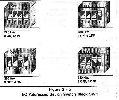
Each QL 3001 board houses a four position DIP switch (SW1). Switches 3 and 4 of SW1 select the base I/O address used by the server driver to communicate with the QL 3001 processors. The QL interface requires eight consecutive I/O ports beginning with the base I/O address.
The I/O addresses selected must not be assigned to any non QL 3000 Series devices installed in the file server or bridge hosting the QL 3000 boards. However, all of the QL 3000 Series boards installed in this host should have the same base I/O address.
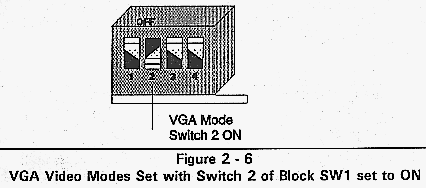
VGA Versions
The VGA versions of the QL 3000 Series boards use autosensing to detect the video type. Leave switch 2 of switch block SW1 ON. Figure 2-6 shows switch block SW1 with switch 2 ON.
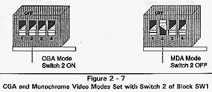
CGA and Monochrome Versions
Previous revisions of the QL 3001 board used either MDA or CGA video mode. Switch 2 of switch block SW1 selects the video mode. Figure 2-7 shows the video modes set with switch block SW1.
The 20 MHz 80386SX on the standard QL 3001 board uses a 20 MHz 80387SX coprocessor. The 25 MHz Cx486SLC uses a 25 MHz Cyrix Cx83S87 coprocessor.
To install a math coprocessor:
	*	Discharge all static electricity from your hand.
	*	Remove the numeric coprocessor from its antistatic
	package.
	*	Align the coprocessor pins with the socket
	connectors.
	*	Ensure that the notch on the chip is aligned with
	the notch on the top left
                        corner of the socket.
	*	Insert the chip.
	*	Press the chip down firmly when it is in place.
	*	Verify that the pins are seated properly.
Figure 2-8
.The QL 3001 boards must be installed in a NetWare file server or an external bridge or router. If the file server or bridge/router already contains QL 3000 Series boards, and the QL software does not need to be updated, simply follow the instructions below to install the new boards. For all other cases, a complete software installation should be performed. Refer to the QL 3000 Series Guide to Operations. To install the boards:
	*	Ensure all boards in the server or bridge are idle.
	*	Perform an orderly shutdown of the server or bridge.
	*	Power down the server or bridge.
	*	Remove the access cover to the bus slots.
	*	Seat the QL 3001 board into a 16bit slot in the
	computer and secure with a
                        screw.
	*	Replace the computer's cover.
	*	Apply power to the server or bridge.
	*	Boot the file server or external bridge.  Be sure
	that the system loads all of
                        the selected LAN drivers, and
                        connects properly to the server.
This document, and all Web contents, Copyright © 1997
by Cubix Corp., Carson City, NV, USA.