MP 2008/2208
Chapter 2 - Hardware Configuration
This section describes how to configure and install the MP Series hardware.
All MP Series adapter boards have a single switch bank labeled SW1 on the top edge of the adapter, near the end bracket. This switch bank consists of eight switches, numbered one through eight. These switches should only be changed while no power is applied to the MP adapter. A switch is in the ON position when it is toward the board.
The switches in bank SW1 set the I/O port address and the logical board number to be used by the MP adapter. Switches 1 and 2 control the I/O port address, while switches 4-8 control the logical board number. Switch 3 is always ON.
The default switch settings for SW1 are all ON.
Base I/O Address Selection
The MP adapter boards require a series of 16 I/O locations to allow communications between the Cubix software driver and the hardware. Switches 1 and 2 of switch bank SW1 set the base I/O address to be used for this I/O address range. The MP boards support four different I/O address ranges (numbers given in hexadecimal):
Table 2 - 1 Base I/O Address Selection
Base I/O Address |
Range |
S-1 |
S-2 |
| default 200 | 200-20F |
ON |
ON |
| 210 | 210-21F |
ON |
OFF |
| 300 | 300-30F |
OFF |
ON |
| 310 | 310-31F |
OFF |
OFF |
Select any base I/O address that does not conflict with other system hardware. Selecting a base I/O address other than the default may affect loading the software driver. Refer to Appendix D - WorldDesk Comlink Installation or Appendix E - Novell/Cubix Connect Installation for software installation details.
Logical Board Number Selection
Each MP Series adapter board installed in a server must be assigned a unique board number among all MP boards in that system. The logical board number is used (along with a port number) to identify individual ports when the software driver is loaded. If two MP Series adapters attempt to use the same logical board number, driver failure will result.
Any board number from zero to fourteen may be selected for use by a board. Assign board numbers sequentially, beginning with board number zero. Switch bank SW1 switches 4-8 are used to set the board number for the hardware. The MP Series software dynamically detects the assigned board numbers. The switch settings for the logical board numbers are listed in Table 2-2.
Table 2 - 2 Board Number Selection
Logical Board |
S-4 |
S-5 |
S-6 |
S-7 |
S-8 |
| default 0 | ON |
ON |
ON |
ON |
ON |
| 1 | ON |
ON |
ON |
ON |
OFF |
| 2 | ON |
ON |
ON |
OFF |
ON |
| 3 | ON |
ON |
ON |
OFF |
OFF |
| 4 | ON |
ON |
OFF |
ON |
ON |
| 5 | ON |
ON |
OFF |
ON |
OFF |
| 6 | ON |
ON |
OFF |
OFF |
ON |
| 7 | ON |
ON |
OFF |
OFF |
OFF |
| 8 | ON |
OFF |
ON |
ON |
ON |
| 9 | ON |
OFF |
ON |
ON |
OFF |
| 10 | ON |
OFF |
ON |
OFF |
ON |
| 11 | ON |
OFF |
ON |
OFF |
OFF |
| 12 | ON |
OFF |
OFF |
ON |
ON |
| 13 | ON |
OFF |
OFF |
ON |
OFF |
| 14 | ON |
OFF |
OFF |
OFF |
ON |
Installation
Before installing an MP adapter board in the system, be sure to turn the system off and disconnect it from the power source. Inserting the MP adapter board into a live server may damage the hardware and injure the installer.
The MP adapter board must be installed in a 16-bit ISA or 32-bit EISA compatible slot. Be sure to observe the overall system power limitations (refer to Appendix A - Hardware Specifications for the MP Series power requirements).
After installation in an available slot, use a screw to secure the end bracket of the MP adapter board to the system chassis. Firm installation of the adapter board helps to ensure that loose connections do not cause system unreliability or hardware damage.
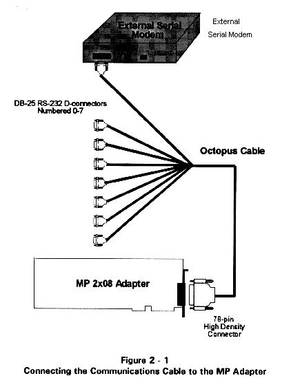
Connect the provided communications cable to the MP adapter as shown in Figure 2 - 1. IT IS VERY IMPORTANT THAT THE HOLD-DOWN SCREWS ON THE CONNECTOR BE FIRMLY ATTACHED TO THE MP ADAPTER. Failure to observe this requirement often results in misalignment of the connector, and intermittent communications signals which can cause abnormal communications session loss (or inhibition of communications).
Verify the installation and configuration of the MP hardware before powering on the system or proceeding to software installation and configuration.

Troubleshooting
The MP adapter provides a rear panel indicator lamp, visible through the bracket, that may be used to confirm that the driver has loaded successfully. The lamp states are:
OFF SOLID indicates that the driver is not present; that is, it has not yet been loaded, or it has been unloaded.
ON/OFF FLASHING indicates that the driver is present and operating normally.
ON SOLID indicates that the board failed self-test or that the software load was unsuccessful.
This document, and all Web contents, Copyright © 1997 by Cubix Corp., Carson City, NV, USA.