Chapter 3
Field Replaceable Units
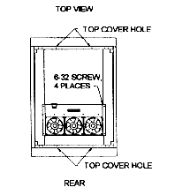
Fan Assembly
Replacement Instructions
- Turn power off and remove power cords.
- Remove the subsystem located at the top of the cabinet.
- Remove top cover. The screws are located inside the cabinet
- two at the front and two at the back.
- Disconnect the power cord to the fan tray.
- Remove the four screws holding the fan tray to the top
support brackets.
- Remove fan tray.
- Reinstall new fan tray.

Figure 3-1, Fan Assembly Replacement
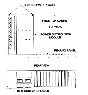
Power Distribution Module
Replacement Instructions
- Turn power off and remove power cords.
- Disconnect all power cords to the power distribution module
and cables to the rear I/O panel.
- Remove subsystems.
- Remove the two screws attaching the power distribution
module to the base pan.
- Remove the four screws mounting the rear I/O panel to the
RETMA rail.
- Remove the power distribution module and the rear I/O panel.
- Reinstall the new power distribution module and rear I/O
panel.

Figure 3-2, Power Distribution Module Replacement
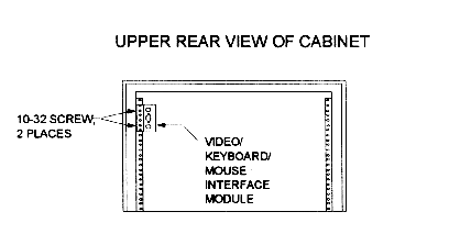
Video/Keyboard/Mouse Interface Module
Replacement Instructions
- Turn power off and remove power cords.
- Open rear door.
- Remove video/keyboard/mouse interface module cables.
- Remove the two screws attaching the interface module to the
rail.
- Reinstall the new video/keyboard/mouse interface module.

Figure 3-3, Video/Keyboard/Mouse Interface Module
Replacement
This document, and all Web contents,
Copyright © 1997 by Cubix Corp., Carson City, NV, USA.


