Chapter 2
Installation
Pre-Installation Inspection
Upon receiving the System 1010 cabinet, perform the following inspection:
Site Preparation
Before installing the System 1010 cabinet, prepare the site:
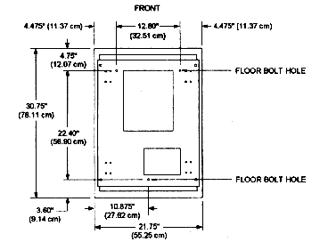
Figure 2-1, Floor Bolt Patttern
Single Cabinet Installation
After following the preinstallation and site preparation, the cabinet is ready to be installed. To install a standalone System 1010, follow the instructions below. Double-wide cabinet installation instructions are provided later in this chapter.
!! CAUTION !!
IF THE CABINET IS NOT SECURED TO THE FLOOR,
THE CABINET MAY TIP OVER WHEN A DRAWER IS EXTENDED.
Cabling Considerations
Internal Power Cords
The System 1010 cabinet (single bay) has two independent AC input power circuits in its AC power distribution assembly. Each power circuit is individually protected by a circuit breaker switch located on the lower rear panel. Each AC input circuit provides power to five output receptacles. Four of these receptacles are used to power rack mounted equipment and one receptacle is reserved for either the fan assembly or an optional monitor power source.
The eight in-line receptacles on the angled surface of the AC power distribution chassis inside the cabinet are divided into two groups: GROUP 1 AC INPUT and GROUP 2 AC INPUT. This is to provide power redundancy to the Cubix Fault Tolerant (ERS/FT) subsystems. Connect ERS/FT power supply number 1 (PS1) input power cords to AC INPUT GROUP 1 and ERS/FT power supply number 2 (PS2) input power cords to AC INPUT GROUP 2 receptacles. In this way, redundancy is maintained from the ERS/FT power supplies out to the AC power branch circuits.
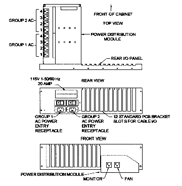
Figure 2-2, 115V Rear AC, I/O and Power Distribution Module
To install power cords in the System 1010, attach and secure the cord to the required rack mounted equipment power inlet. Then dress the cord down the left side of the cabinet (looking from the rear) between the outside cover and the drawer slide rails. In an ERS/FT installation, plug the cord from PS1 on the ERS/FT rear I/O panel to an outlet in GROUP 1 AC.
Route the cord from PS2 of the ERS/FT rear I/O panel alongside the first cord and plug it into an outlet in GROUP 2 AC.
Plug the power cord from the fan assembly into the power distribution module receptacle marked "FAN". This receptacle is connected to the Group 1 AC input. A video monitor may be connected to the power distribution module at the receptacle marked "MONITOR". This receptacle is connected to GROUP 2 AC INPUT.
External Power Cords
115VAC
Systems configured for 115VAC should use the power cords supplied with the System 1010. Refer to the Electrical Specifications in Appendix A for cord requirements. Attach one cord from a 115VAC outlet to the Group 1 AC Power Entry Receptacle on the System 1010 and the second cord from a 115VAC outlet to the Group 2 AC Power Entry Receptacle (refer to Figure 2-2).
240VAC
A System 1010 configured for 240VAC operation is supplied with 2 cable connectors for power entry. These connectors mate with the Group 1 AC Power Entry Receptacle and the Group 2 Power Entry Receptacle of the System 1010 (refer to Figure 2-2). The user must provide a cord and plug to be wired to these connectors. Cord specifications are included in Appendix A. Refer to Figure 2-3 for wiring instructions.
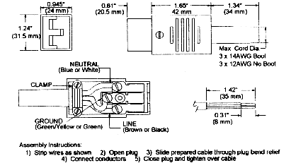
Figure 2-3, 240V Power Cord Wiring
12 Slot Rear I/O Panel
The I/O panel is located to the right of the AC input receptacles at the lower rear of the System 1010 cabinet. 12 slots are provided which accept industry standard end brackets for external signal interfacing. Cabling from the rack mounted equipment should be routed down the right cabinet wall (looking from the rear) to the I/O panel. In addition to the 12 slot I/O, there is a cable opening in the base of the cabinet.
Multiplexing
ERS, ERS/FT and Series II subsystems contain integrated multiplexors which allow a single monitor, keyboard, and mouse to be shared among multiple processors installed in a subsystem. Since one System 1010 can contain multiple subsystems, there is a need to "multiplex" between the subsystems, thus allowing a single monitor, keyboard, and mouse to service all processors installed in a System 1010.
Multiplexing between ERS/FT and/or Series II subsystems is accomplished by "daisy-chaining" between subsystems and connecting the end of the chain to a special interface module located on the upper right rear rail of the System 1010 (refer to Figure 2-4). The monitor, keyboard, and mouse are also connected to this interface module, allowing them to be shared between all ERS/FT and Series II subsystems in the chain.
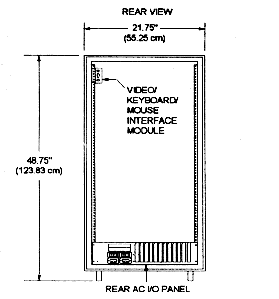
Figure 2-4, Video/Keyboard/Mouse Interface Module
ERS subsystems, however, cannot be daisy chained together. Therefore, to share a monitor, keyboard and mouse between ERS subsystems requires that an additional multiplexor be installed. This multiplexor is described as the cabinet mux. The monitor, keyboard, and mouse connectors on each ERS are attached to the cabinet mux. The monitor, keyboard, and mouse are also connected to the cabinet mux. The cabinet mux multiplexes between the ERS subsystems.
If there is a need to share a monitor, keyboard, and mouse between ERS and ERS/FT or Series II subsystems installed in the same System 1010, a combination of the two methods previously described must be used. A cabinet mux is required, and it is connected to the monitor, keyboard, and mouse. The ERS subsystems are connected to the cabinet mux. The ERS/FT and Series II subsystems are daisy chained to the System 1010 interface module (refer to Figure 2-4). This interface module is connected to the cabinet mux.
ERS/FT and Series II
To multiplex between ERS/FT subsystems, connect a 25 conductor DB-25 male to DB-25 male cable to the 25 pin connector labeled Video/KB/Mouse on the System 1010 cabinet's interface module. Connect the other end of the cable to the 25 pin connector labeled "VIDEO OUT" on the rear panel of an ERS/FT. The VGA video, keyboard, and mouse peripheral cables may be inserted into the cabinet through the hole in the top cover and then connected to the appropriate connector as labeled on the interface module.
ERS
To multiplex between ERS subsystems requires a cabinet mux. Connect two cables from each ERS mux output to one cabinet mux input. Connect the monitor, keyboard, and mouse to the cabinet mux output.
ERS and ERS/FT or Series II
Sharing a monitor, keyboard, and mouse between both ERS/FT and ERS subsystems also requires a cabinet mux. First cable the ERS/FT subsystems to the System 1010 interface module as previously explained. Connect the interface module to the cabinet mux (input). Connect each ERS mux output to one cabinet mux input. Connect the monitor, keyboard, and mouse to the cabinet mux output.
Mouse Drivers for Logitech Mouse Devices
As previously mentioned, a mouse input device may be multiplexed between multiple Cubix processors. This allows a single mouse device to be shared between all of the BC processors installed in a system. The support provided is for PS/2 style mouse devices.
Each Cubix processor is equipped with a mouse controller. Corruption of the data stream between the mouse and the mouse controller can occur if the multiplexor channel is changed while a data transfer is in progress. Mouse data corruption is manifested by:
To minimize the aggravation caused by mouse data corruption, Cubix has included mouse support software for Logitech mouse devices. Software drivers are provided for DOS, Windows, and OS/2 environments. Refer to the BC Series documentation for software installation and operation instructions.
When using the Cubix mouse software, recovery from multiplexed mouse faults has been successfully tested with Logitech mouse products. Cubix recommends the use of Logitech mouse products in multiplexed environments.
Monitor Power
The video monitor may be powered via the auxiliary outlet attached to AC INPUT GROUP 2 by passing the monitor's power through the hole in the top cover and then connecting the plug to the monitor receptacle on the AC power distribution assembly.
!! CAUTION !!
VOLTAGE AT THE MONITOR POWER RECEPTACLE IS 240VAC IN SYSTEMS CONFIGURED FOR 240VAC INPUT OPERATION. VERIFY THAT THE INPUT VOLTAGE RATING OF THE MONITOR MATCHES THE INPUT VOLTAGE RATING OF THE SYSTEM 1010 BEFORE CONNECTING THE MONITOR POWER CORD TO THE SYSTEM 1010 MONITOR RECEPTACLE.
Double-Wide Cabinet Installation
The System 1010 double-wide option joins two cabinets together for additional rack space.
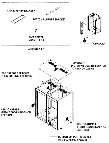
Figure 2-5, Assembly Instructions for Double-wide System 1010 Cabinet
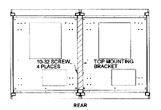
Figure 2-6, Cross Section of Bottom
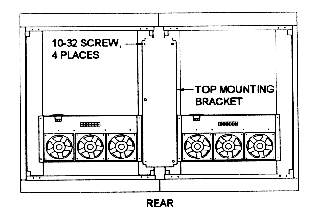
Figure 2-7, Top View
This document, and all Web contents, Copyright © 1997 by Cubix Corp., Carson City, NV, USA.