Manuale utente del Commodore 128
Scansionato da Vincenzo Scarpa
The Commodore 128 existed in three different major board versions:
The first board was used in the flat 128 and in the plastic-cased 128D.
Then came the 128DCR board, with the floppy controller integrated on the
motherboard. There was also a 128CR (cost-reduced flat 128).
- 310378-1-left.gif
1996-11-27
118674
-
- 310378-1-right.gif
1996-11-27
113712
-
- 310378-2-left.gif
1996-11-27
99301
-
- 310378-2-right.gif
1996-11-27
107805
-
- 310378-3-left.gif
1996-11-27
130766
-
- 310378-3-right.gif
1996-11-27
77337
-
- 310378-4-left.gif
1996-11-27
99507
-
- 310378-4-right.gif
1996-11-27
90149
- These are the schematic diagrams of the Commodore 128 main board
("flat C128" and C128D in plastic case). They were on eight pages
in the Commodore 128 Programmer's Reference Guide, two pages
containing one engineering sheet.
- 310378-update.zip
1998-05-15
747229
- Update to the Commodore 128 Service Manual, containing the two revised
pages in the 310378 schematic revision 7A.
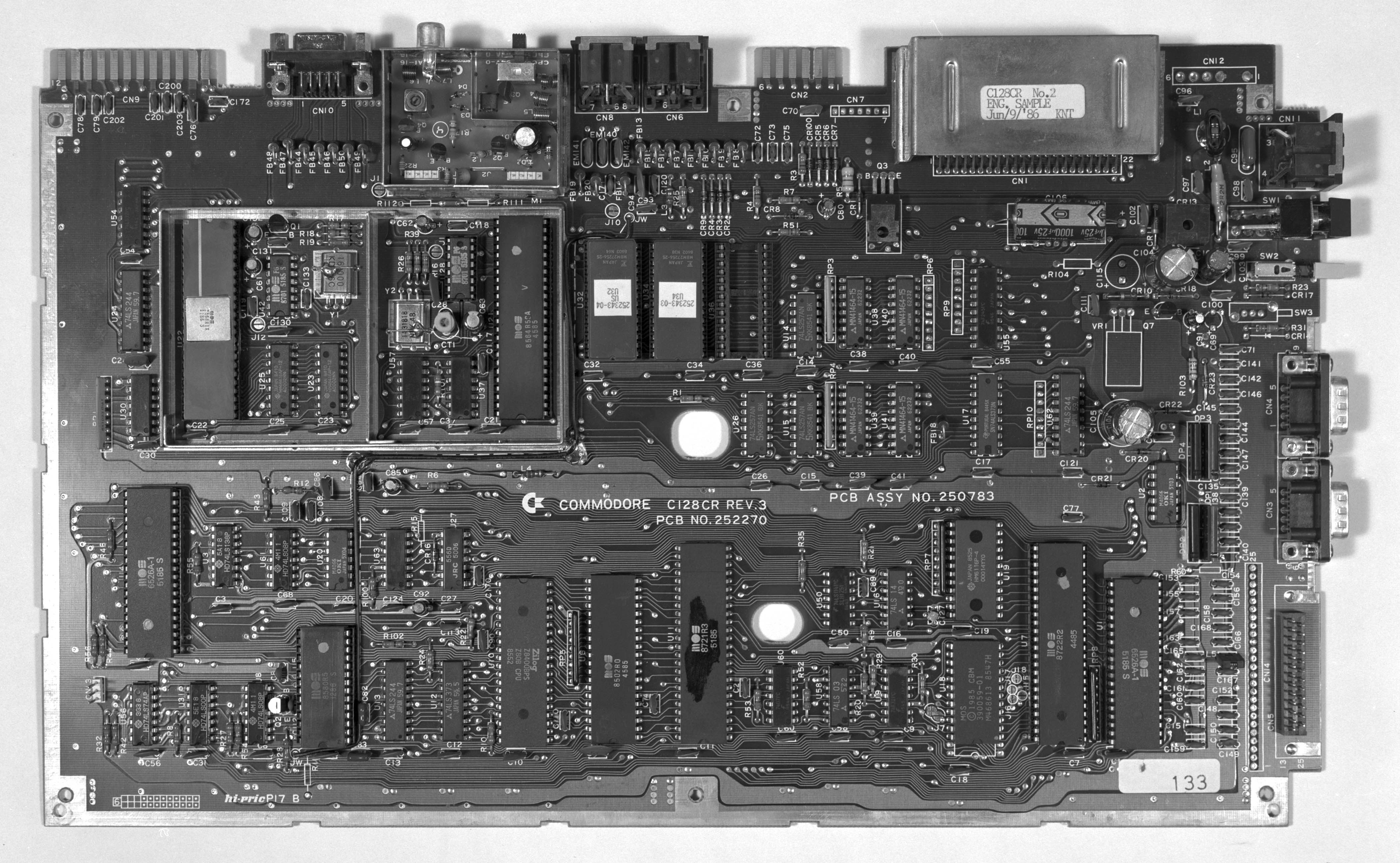
- c128cr.jpg
2000-02-23
1115174
- A black&white picture of a cost-reduced flat Commodore 128 circuit board.
This model never entered mass production; this is an engineering sample
possessed by Raymond Carlsen. The board says "PCB ASSY NO. 250783",
"C= commodore C128CR REV.3", "PCB NO. 252270", and "C128CR No.2
ENG. SAMPLE Jun/9/'86 KNT".
- c128dcr-1-left.gif
1996-12-13
172416
-
- c128dcr-1-right.gif
1996-12-13
90870
-
- c128dcr-2-left.gif
1996-12-13
143437
-
- c128dcr-2-right.gif
1996-12-13
148206
-
- c128dcr-3-left.gif
1996-12-13
128384
-
- c128dcr-3-right.gif
1996-12-13
134398
-
- c128dcr-4-left.gif
1996-12-13
77902
-
- c128dcr-4-right.gif
1996-12-13
58823
-
- c128dcr-5-left.gif
1996-12-13
126315
-
- c128dcr-5-right.gif
1996-12-13
144315
- These are the schematic diagrams of the Commodore 128DCR main board
(metal case C128D with built-in 1571CR floppy controller). The diagrams
were scanned from a 64'er Sonderheft, and they appear to be a copy of
schematic 252451.
According to Nicolas Welte, there is an error on the right half of page 5.
The 74LS14 hex Schmitt-trigger inverter U113, pin 13 is connected to WPRT*
(misprinted WTRT* on U105), which doesn't make any sense. Obviously it
should be connected to STP1 instead, which is three lines more to the right!
Mirror sites
–
General information
–
File types
–
Data transfer
The Commodore brandname and the chickenhead logo are
property of Commodore International Corp.